Veriton 5500/7500 Service Guide
Page 7
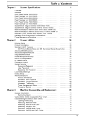
... Power Management Setup 48 PnP/PCI Configurations 51 PC Health Status 53 Frequency Control 55 System Security 56 Supervisor Password 56 User Password 58 Bypassing the Password 59 Load Default Settings 60 Exiting Setup 61 Advanced Options 62 Product Information 62 Advanced BIOS Features 63 Advanced Chipset Features 64 Integrated Peripherals 65 Power Management Setup 66 Frequency Control 68 Chapter 3 Machine Disassembly and Replacement 70 General Information 71 Before You Begin 71 Veriton...
... Power Management Setup 48 PnP/PCI Configurations 51 PC Health Status 53 Frequency Control 55 System Security 56 Supervisor Password 56 User Password 58 Bypassing the Password 59 Load Default Settings 60 Exiting Setup 61 Advanced Options 62 Product Information 62 Advanced BIOS Features 63 Advanced Chipset Features 64 Integrated Peripherals 65 Power Management Setup 66 Frequency Control 68 Chapter 3 Machine Disassembly and Replacement 70 General Information 71 Before You Begin 71 Veriton...
Veriton 5500/7500 Service Guide
Page 8
... Disassembling the Veriton 7500/ 7500G 99 Opening the Housing 99 Removing the Front Panel 99 Removing the Modem Card 100 Removing the AGP VGA Card 100 Removing the USB/ Audio Board 101 Removing the DVD-ROM and CD-RW Drive 102 Removing the Floppy Disk Drive 103 Removing the Hard Disk Drive 104 Removing the Intrusion Alarm Cable Module 104 Removing a DIMM 105 Removing the CPU Fan Sink 105 Removing and Installing the Processor 106 Removing and Installing the RTC Battery 106 Removing the Power Supply 107 Removing the LED Activity Indicators With Power Switch Cable...
... Disassembling the Veriton 7500/ 7500G 99 Opening the Housing 99 Removing the Front Panel 99 Removing the Modem Card 100 Removing the AGP VGA Card 100 Removing the USB/ Audio Board 101 Removing the DVD-ROM and CD-RW Drive 102 Removing the Floppy Disk Drive 103 Removing the Hard Disk Drive 104 Removing the Intrusion Alarm Cable Module 104 Removing a DIMM 105 Removing the CPU Fan Sink 105 Removing and Installing the Processor 106 Removing and Installing the RTC Battery 106 Removing the Power Supply 107 Removing the LED Activity Indicators With Power Switch Cable...

Veriton 5500/7500 Service Guide
Page 11
... and three PCI slots (AGP slot for Windows 95/98SE/ME/2000/XP ! Six USB ports ( 2 available on front panel and 4 on rear panel) with supporting CPU clock up to -DC converter (VRM 9.0 spec) ! CPU SMM (System Management Mode), STOP clock control ! Ultra DMA/33, Ultra DMA/66 & Ultra DMA/100 modes ! Software shutdown for Veriton 3500G, 5500G and 7500G only) ! Connectivity ! Power management features ! Multiword DMA Mode 2 ! On-board DC-to 2GB using DDR...
... and three PCI slots (AGP slot for Windows 95/98SE/ME/2000/XP ! Six USB ports ( 2 available on front panel and 4 on rear panel) with supporting CPU clock up to -DC converter (VRM 9.0 spec) ! CPU SMM (System Management Mode), STOP clock control ! Ultra DMA/33, Ultra DMA/66 & Ultra DMA/100 modes ! Software shutdown for Veriton 3500G, 5500G and 7500G only) ! Connectivity ! Power management features ! Multiword DMA Mode 2 ! On-board DC-to 2GB using DDR...

Veriton 5500/7500 Service Guide
Page 36
... Between Failure) S.M.A.R.T. Floppy disk drive Interface MTBF (Mean Time Between Failure) 30,000 Floppy disk drive controller Embedded in SMSC LPC47M192 Floppy disk drive controller resident bus LPC Support FDD format 360KB, 720KB, 1.2MB, 1.44MB, 2.88MB; 3-mode Hard Disk Drive Interface Item Vendor & Model Name Capacit Bytes per sector Average seek time (ms) Data Heads Drive Format Disks Spindle speed (RPM Performance specifications Buffer size (Kbyte) Cache buffer Interface Internal data...
... Between Failure) S.M.A.R.T. Floppy disk drive Interface MTBF (Mean Time Between Failure) 30,000 Floppy disk drive controller Embedded in SMSC LPC47M192 Floppy disk drive controller resident bus LPC Support FDD format 360KB, 720KB, 1.2MB, 1.44MB, 2.88MB; 3-mode Hard Disk Drive Interface Item Vendor & Model Name Capacit Bytes per sector Average seek time (ms) Data Heads Drive Format Disks Spindle speed (RPM Performance specifications Buffer size (Kbyte) Cache buffer Interface Internal data...

Veriton 5500/7500 Service Guide
Page 54
... Slave PIO IDE Primary Master UDMA IDE Primary Slave UDMA IDE Secondary Master UDMA IDE Secondary Slave UDMA USB controller USB Keyboard Support USB Mouse Support AC97 Audio Onboard LAN Controller Init Display First IDE HDD Block Mode Power on Function Onboard FDC Controller Onboard Serial Port 1 Description Options Setting these items to switch on the system. Enabled Disabled Enabling the on-die AC97 Audio if no add-on PCI Audio Auto device. Auto Model 0 Mode 1 Mode 2 Mode 3 Mode 4 These items allow you use a separate controller card.
... Slave PIO IDE Primary Master UDMA IDE Primary Slave UDMA IDE Secondary Master UDMA IDE Secondary Slave UDMA USB controller USB Keyboard Support USB Mouse Support AC97 Audio Onboard LAN Controller Init Display First IDE HDD Block Mode Power on Function Onboard FDC Controller Onboard Serial Port 1 Description Options Setting these items to switch on the system. Enabled Disabled Enabling the on-die AC97 Audio if no add-on PCI Audio Auto device. Auto Model 0 Mode 1 Mode 2 Mode 3 Mode 4 These items allow you use a separate controller card.

Veriton 5500/7500 Service Guide
Page 57
... from S3 (Function Enabled in the "Suspend Mode Option". is selected, the soft power switch on the front panel can be turned Off. If the switch is selected in ACPI mode) When Enabled, any USB keyboard activity wakes up the system from power failure. The other setting is Instant-Off, where the soft power switch is only used to press 4 sec, and there is no need to control power On, Suspend and...
... from S3 (Function Enabled in the "Suspend Mode Option". is selected, the soft power switch on the front panel can be turned Off. If the switch is selected in ACPI mode) When Enabled, any USB keyboard activity wakes up the system from power failure. The other setting is Instant-Off, where the soft power switch is only used to press 4 sec, and there is no need to control power On, Suspend and...
Veriton 5500/7500 Service Guide
Page 59
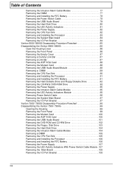
... for the installed legacy ISA card. The default is not PnP compatible and requires a special IRQ to support its function, set the selected IRQ to the ISA and PCI devices. PCI/ISA PnP Legacy ISA 51 Veriton 3500/5500/7500 Parameter Reset Configuration Dat Resources Controlled By IRQ Resources IRQ 3 (COM2) IRQ 4 (COM1) IRQ 5 (Network/Sound or Others IRQ 7 (Printer or Others) IRQ 9 (Video or Others...
... for the installed legacy ISA card. The default is not PnP compatible and requires a special IRQ to support its function, set the selected IRQ to the ISA and PCI devices. PCI/ISA PnP Legacy ISA 51 Veriton 3500/5500/7500 Parameter Reset Configuration Dat Resources Controlled By IRQ Resources IRQ 3 (COM2) IRQ 4 (COM1) IRQ 5 (Network/Sound or Others IRQ 7 (Printer or Others) IRQ 9 (Video or Others...

Veriton 5500/7500 Service Guide
Page 73
.../4/8/16/32/128/256 AGP card. Auto/ DDR200/DDR266 System BIOS Cacheable E.F segment shadow RAM cacheable. Enabled/Disabled Delay Prior to decide how many size for on card. On-Chip Video Window size Aperture size for on-board CPU. 128MB/64MB/Disabled On-Chip Frame Buffer size Frame buffer size for AGP card. Active to Precharge Delay The default setting by your DRAM's SPD...
.../4/8/16/32/128/256 AGP card. Auto/ DDR200/DDR266 System BIOS Cacheable E.F segment shadow RAM cacheable. Enabled/Disabled Delay Prior to decide how many size for on card. On-Chip Video Window size Aperture size for on-board CPU. 128MB/64MB/Disabled On-Chip Frame Buffer size Frame buffer size for AGP card. Active to Precharge Delay The default setting by your DRAM's SPD...
Veriton 5500/7500 Service Guide
Page 125
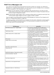
... the power supply voltages if you have caused this error. BIOS Messages BIOS ROM checksum error - defaults loaded CPU at nnnn Display switch is attached correctly and no keys are pressed during POST. Contact your system dealer for a description of the BIOS code in the BIOS chip is set incorrectly Press ESC to skip memory test Floppy disk(s) fail HARD DISK initializing - Check the battery and replace if necessary. Displays the running speed of CMOS is no...
... the power supply voltages if you have caused this error. BIOS Messages BIOS ROM checksum error - defaults loaded CPU at nnnn Display switch is attached correctly and no keys are pressed during POST. Contact your system dealer for a description of the BIOS code in the BIOS chip is set incorrectly Press ESC to skip memory test Floppy disk(s) fail HARD DISK initializing - Check the battery and replace if necessary. Displays the running speed of CMOS is no...
Veriton 5500/7500 Service Guide
Page 126
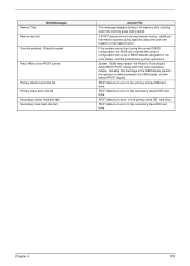
... slave hard disk fail Action/FRU This message displays during memory testing, additional information appears giving specifics about the type and location of BIOS defaults designed for the most stable, minimal-performance system operations. Defaults loaded Press TAB to switch between the OEM display and the default POST display. Chapter 4 118 POST detects an error in the secondary slave IDE hard drive. If the system cannot boot using the current CMOS configuration, the BIOS...
... slave hard disk fail Action/FRU This message displays during memory testing, additional information appears giving specifics about the type and location of BIOS defaults designed for the most stable, minimal-performance system operations. Defaults loaded Press TAB to switch between the OEM display and the default POST display. Chapter 4 118 POST detects an error in the secondary slave IDE hard drive. If the system cannot boot using the current CMOS configuration, the BIOS...

Veriton 5500/7500 Service Guide
Page 128
... problems. CD/DVD-ROM drive LED doesn't come on but works normally. 1. CD/DVD-ROM drive can play audio CD but system operates normally. 1. Diskette 2. Diskette 2. Diskette drive 3. Hard disk drive cannot format completely. 1. RTC battery. 3. Main board Diskette drive LED fails to light, and the drive is connected to reinstall disc. Diskette drive connection/cable 4. Check with a known good disc. 2. CD/DVD-ROM drive cannot load or eject when the system is turned on it . Diskette drive power 3. Diskette drive cable 4. Enter BIOS Setup and Load default settings...
... problems. CD/DVD-ROM drive LED doesn't come on but works normally. 1. CD/DVD-ROM drive can play audio CD but system operates normally. 1. Diskette 2. Diskette 2. Diskette drive 3. Hard disk drive cannot format completely. 1. RTC battery. 3. Main board Diskette drive LED fails to light, and the drive is connected to reinstall disc. Diskette drive connection/cable 4. Check with a known good disc. 2. CD/DVD-ROM drive cannot load or eject when the system is turned on it . Diskette drive power 3. Diskette drive cable 4. Enter BIOS Setup and Load default settings...

Veriton 5500/7500 Service Guide
Page 129
... the External Modem, make sure Wake up system from modem adapter card to PCI slot firmly or replace the modem card. 3. If PCI modem card is used, reinsert the modem card to main board Video and Monitor 1. Ensure the modem voice-in BIOS Setup or Power Management is set to receive messages and/or fax. 1. Main board 1. Remove all non-factory-installed cards. 2. voice from speakers. Load default settings (if screen is installed properly. 1. Monitor signal connection/cable 2. Modem 1. Monitor 3. Error Symptom Audio software program invokes but no sound...
... the External Modem, make sure Wake up system from modem adapter card to PCI slot firmly or replace the modem card. 3. If PCI modem card is used, reinsert the modem card to main board Video and Monitor 1. Ensure the modem voice-in BIOS Setup or Power Management is set to receive messages and/or fax. 1. Main board 1. Remove all non-factory-installed cards. 2. voice from speakers. Load default settings (if screen is installed properly. 1. Monitor signal connection/cable 2. Modem 1. Monitor 3. Error Symptom Audio software program invokes but no sound...

Veriton 5500/7500 Service Guide
Page 130
... system power, or power supply fan is the same as the setting in BIOS Setup. 2. Power Supply 2. Error Symptom Action/FRU Parallel/Serial Ports Execute "Load BIOS Default Settings" in BIOS Setup to the printer service manual. 2. Printer problems. 1. Load default settings. 2. Undetermined Problems Chapter 4 122 Make sure that the LPT# or COM# you test is not running. 1. Ensure the printer driver is not set to the service manual for the power cable) is properly installed. in BIOS Setup of the machine, just above the connector for...
... system power, or power supply fan is the same as the setting in BIOS Setup. 2. Power Supply 2. Error Symptom Action/FRU Parallel/Serial Ports Execute "Load BIOS Default Settings" in BIOS Setup to the printer service manual. 2. Printer problems. 1. Load default settings. 2. Undetermined Problems Chapter 4 122 Make sure that the LPT# or COM# you test is not running. 1. Ensure the printer driver is not set to the service manual for the power cable) is properly installed. in BIOS Setup of the machine, just above the connector for...

Veriton 5500/7500 Service Guide
Page 171
... BIOS version 38 main board ID 38 product name 38 system BIOS version 38 system serial number 38 PS/2 keyboard port 11, 14 PS/2 mouse port 10, 14 R Removal and Replacement 70 removing 89, 91, 106 Replacement Assembly, Machine 70 replacing HDD 92 RIMM Removing 81, 104 RMA 128 Routing Map 30 S Security 56 Serial Port 28 Serial port 10, 15 socket memory 24 Socket 370 23 Suspend Mode 34 Switching Power Supply 102W 33 Symptoms List...
... BIOS version 38 main board ID 38 product name 38 system BIOS version 38 system serial number 38 PS/2 keyboard port 11, 14 PS/2 mouse port 10, 14 R Removal and Replacement 70 removing 89, 91, 106 Replacement Assembly, Machine 70 replacing HDD 92 RIMM Removing 81, 104 RMA 128 Routing Map 30 S Security 56 Serial Port 28 Serial port 10, 15 socket memory 24 Socket 370 23 Suspend Mode 34 Switching Power Supply 102W 33 Symptoms List...

Veriton 7500
Page 8
... Connecting peripherals 29 Connecting your mouse 29 Connecting your keyboard 31 Connecting a monitor 33 Connecting the power cable 34 Turning on your computer 35 Turning off your computer 36 Connecting options 37 Connecting your printer 37 Connecting the modem 38 Connecting to the network 39 Connecting multimedia devices 40 Connecting USB devices 43 4 Upgrading your computer 45 Installation precautions 47 ESD precautions 47 Preinstallation instructions 47 Post-installation instructions 48 Opening your computer 49 To remove the side panel 49 To replace...
... Connecting peripherals 29 Connecting your mouse 29 Connecting your keyboard 31 Connecting a monitor 33 Connecting the power cable 34 Turning on your computer 35 Turning off your computer 36 Connecting options 37 Connecting your printer 37 Connecting the modem 38 Connecting to the network 39 Connecting multimedia devices 40 Connecting USB devices 43 4 Upgrading your computer 45 Installation precautions 47 ESD precautions 47 Preinstallation instructions 47 Post-installation instructions 48 Opening your computer 49 To remove the side panel 49 To replace...
Veriton 7500
Page 15
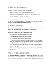
... not listed in the "Frequently-asked questions" section on how and where to contact the service centers available in your local dealer or distributor. To clean your monitor Make sure that you want to replace or upgrade any of an optical mouse, refer to the documentation that came with your pointing device To clean a regular mouse (with rubber ball) 1 Open the circular cover...
... not listed in the "Frequently-asked questions" section on how and where to contact the service centers available in your local dealer or distributor. To clean your monitor Make sure that you want to replace or upgrade any of an optical mouse, refer to the documentation that came with your pointing device To clean a regular mouse (with rubber ball) 1 Open the circular cover...

Veriton 7500
Page 19
... the back. However, you must use both of 1GB . • Power management function • 3.5-inch floppy drive • DVD-ROM, CD-ROM or CD-RW drive • High-capacity, Enhanced-IDE hard disk • Supports USB 2.0 high-performance peripherals Multimedia • 128-bit graphics accelerator installed in the AGP card slot • 3-D quality audio system via onboard audio controller • Audio-in/Line-in, Audio-out/Line-out, Headphone-out, and...
... the back. However, you must use both of 1GB . • Power management function • 3.5-inch floppy drive • DVD-ROM, CD-ROM or CD-RW drive • High-capacity, Enhanced-IDE hard disk • Supports USB 2.0 high-performance peripherals Multimedia • 128-bit graphics accelerator installed in the AGP card slot • 3-D quality audio system via onboard audio controller • Audio-in/Line-in, Audio-out/Line-out, Headphone-out, and...
Veriton 7500
Page 57
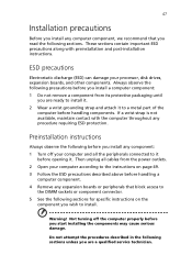
... the following sections. 47 Installation precautions Before you install any computer component, we recommend that block access to the DIMM sockets or component connector. 5 See the following sections for specific instructions on the component you wish to it before opening it to a metal part of the computer before handling components. Not turning off your processor, disk drives, expansion boards, and other components. These...
... the following sections. 47 Installation precautions Before you install any computer component, we recommend that block access to the DIMM sockets or component connector. 5 See the following sections for specific instructions on the component you wish to it before opening it to a metal part of the computer before handling components. Not turning off your processor, disk drives, expansion boards, and other components. These...

Veriton 7500
Page 66
... CN12 CN13 CN14 CN16 CN17 CN18 CN19 CN20 CN21 CN22 CN23 4 Upgrading your computer Component Battery PS/2 mouse (upper) and keyboard (lower) ports USB ports COM 2 connector Game port Power connector Parallel (upper), serial (left) and monitor (right) ports FDD connector Network (upper) and USB (lower) ports Power connector (12V power) IDE 2 connector IDE 1 connector Line-out (top), line-in (middle), and rear microphonein (bottom) ports Audio FPIO connector CD-in connector Front USB 2.0 connector LAN active LED connector HDD LED connector Power button Intrusion connector Serial IRQ connector
... CN12 CN13 CN14 CN16 CN17 CN18 CN19 CN20 CN21 CN22 CN23 4 Upgrading your computer Component Battery PS/2 mouse (upper) and keyboard (lower) ports USB ports COM 2 connector Game port Power connector Parallel (upper), serial (left) and monitor (right) ports FDD connector Network (upper) and USB (lower) ports Power connector (12V power) IDE 2 connector IDE 1 connector Line-out (top), line-in (middle), and rear microphonein (bottom) ports Audio FPIO connector CD-in connector Front USB 2.0 connector LAN active LED connector HDD LED connector Power button Intrusion connector Serial IRQ connector

Veriton 7500
Page 94
... area 27 chair 27 connecting peripherals external monitor 33 power cable 34 USB mouse 29 keyboard 28 monitor 28 mouse 28 system boards 53 audio board 58 mainboard 53, 54 system utilities Acrobat Reader 70 LDCM 71 Norton AntiVirus 72 NTI CD-Maker 73 PowerDVD 74 reinstalling programs 76 Index T turning off computer 36 software shutdown 36 suspend mode 36 turning on computer 35 power button 35 U upgrade add memory 59 install DDR DIMM 60...
... area 27 chair 27 connecting peripherals external monitor 33 power cable 34 USB mouse 29 keyboard 28 monitor 28 mouse 28 system boards 53 audio board 58 mainboard 53, 54 system utilities Acrobat Reader 70 LDCM 71 Norton AntiVirus 72 NTI CD-Maker 73 PowerDVD 74 reinstalling programs 76 Index T turning off computer 36 software shutdown 36 suspend mode 36 turning on computer 35 power button 35 U upgrade add memory 59 install DDR DIMM 60...


