
Acer Veriton M6618G Desktop Service Guide
Page 7
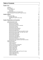
... Specifications and Configurations 9 Power Management Function(ACPI support function) 12 System Utilities 13 CMOS Setup Utility 13 Entering CMOS setup 14 Navigating Through the Setup Utility 14 Main 15 System Disassembly and Assembly 25 Disassembly Requirements 25 Pre-disassembly Procedure 26 Removing the Side Panel 27 Removing the Front Bezel 28 Removing the Heat Sink Fan Assembly 29 Removing the Processor 31 Removing the VGA Card 33 Removing the Memory Modules 34 Removing the Hard Disk Drive 35 Removing the Optical Drive 37 Removing the Printer Port Cable...
... Specifications and Configurations 9 Power Management Function(ACPI support function) 12 System Utilities 13 CMOS Setup Utility 13 Entering CMOS setup 14 Navigating Through the Setup Utility 14 Main 15 System Disassembly and Assembly 25 Disassembly Requirements 25 Pre-disassembly Procedure 26 Removing the Side Panel 27 Removing the Front Bezel 28 Removing the Heat Sink Fan Assembly 29 Removing the Processor 31 Removing the VGA Card 33 Removing the Memory Modules 34 Removing the Hard Disk Drive 35 Removing the Optical Drive 37 Removing the Printer Port Cable...
Acer Veriton M6618G Desktop Service Guide
Page 8
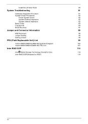
Install the Lift Side Panel 80 System Troubleshooting 81 Hardware Diagnostic Procedure 81 System Check Procedures 82 Power System Check 82 System External Inspection 82 System Internal Inspection 82 Beep Codes 83 Checkpoints 84 BIOS Recovery 87 Jumper and Connector Information 88 M/B Placement 88 Jumper Setting 90 Setting Jumper 90 FRU (Field Replaceable Unit) List 99 Veriton M6610/M6610G/M6618G Exploded Diagram 100 Veriton M6610/M6610G/M6618G FRU List 101 Inter RIAD SOP 114 ® Inter Matrix...
Install the Lift Side Panel 80 System Troubleshooting 81 Hardware Diagnostic Procedure 81 System Check Procedures 82 Power System Check 82 System External Inspection 82 System Internal Inspection 82 Beep Codes 83 Checkpoints 84 BIOS Recovery 87 Jumper and Connector Information 88 M/B Placement 88 Jumper Setting 90 Setting Jumper 90 FRU (Field Replaceable Unit) List 99 Veriton M6610/M6610G/M6618G Exploded Diagram 100 Veriton M6610/M6610G/M6618G FRU List 101 Inter RIAD SOP 114 ® Inter Matrix...
Acer Veriton M6618G Desktop Service Guide
Page 10
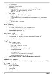
... VGA • DVMT 5.0 technology support • Enhanced 3D and Clear Video technology support • 1 D-sub VGA port on rear • 1 DVI-D port at rear side • 1 Display port on rear • Dual View function support (Should provide priority list) • Need to measure VGA follow Acer VGA SOP • Monitor compatible is listed on AVLC. Optical disk drive • Support SATA 5.25" standard ODD. • Support DVD-ROM, DVD-SuperMulti (Label Flash), BD-DVD, BD-Combo. • Dual channel support • Support Intel Flex Memory Mode • Capacity support...
... VGA • DVMT 5.0 technology support • Enhanced 3D and Clear Video technology support • 1 D-sub VGA port on rear • 1 DVI-D port at rear side • 1 Display port on rear • Dual View function support (Should provide priority list) • Need to measure VGA follow Acer VGA SOP • Monitor compatible is listed on AVLC. Optical disk drive • Support SATA 5.25" standard ODD. • Support DVD-ROM, DVD-SuperMulti (Label Flash), BD-DVD, BD-Combo. • Dual channel support • Support Intel Flex Memory Mode • Capacity support...
Acer Veriton M6618G Desktop Service Guide
Page 11
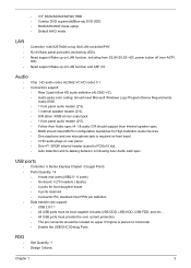
...; Connector Pin: standard Intel FPIO pin definition • Data transfer rate support: • USB 2.0/1.1 • All USB ports must be located on horizontal. • Enable the USB EHCI Debug Ports FDD • • Slot Quantity: 1 Design Criteria: Chapter 1 3 Need support Wake up on LAN function and ASF 2.0. RJ-45 Back panel port with Link/Activity LEDs. • 3.5" SATA/SATAII/SATAIII HDD • Combo/ DVD supermulti/Blue-ray DVD ODD • RAID/AHCI/IDE mode option • Default...
...; Connector Pin: standard Intel FPIO pin definition • Data transfer rate support: • USB 2.0/1.1 • All USB ports must be located on horizontal. • Enable the USB EHCI Debug Ports FDD • • Slot Quantity: 1 Design Criteria: Chapter 1 3 Need support Wake up on LAN function and ASF 2.0. RJ-45 Back panel port with Link/Activity LEDs. • 3.5" SATA/SATAII/SATAIII HDD • Combo/ DVD supermulti/Blue-ray DVD ODD • RAID/AHCI/IDE mode option • Default...
Acer Veriton M6618G Desktop Service Guide
Page 12
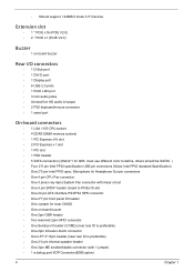
... Specification) • One 2*5 pin Intel FPIO spec. must use different color to PCIEx16 slot • One 24 pin ATX interface PS3/PS2 SPS connector. • One 2*7 pin front panel IO header • One Jumper for clear CMOS • One on board buzzer Rear I/O connectors • 1 D-Sub port • 1 DVI-D port • 1 Display port • 6 USB 2.0 ports • 1 RJ45 LAN port • 3 mini audio jacks • At least five HD audio in/output • 2 PS2 keyboard/mouse connector • 1 serial port...
... Specification) • One 2*5 pin Intel FPIO spec. must use different color to PCIEx16 slot • One 24 pin ATX interface PS3/PS2 SPS connector. • One 2*7 pin front panel IO header • One Jumper for clear CMOS • One on board buzzer Rear I/O connectors • 1 D-Sub port • 1 DVI-D port • 1 Display port • 6 USB 2.0 ports • 1 RJ45 LAN port • 3 mini audio jacks • At least five HD audio in/output • 2 PS2 keyboard/mouse connector • 1 serial port...
Acer Veriton M6618G Desktop Service Guide
Page 16
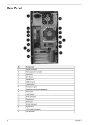
Rear Panel No. Component 1 Power connector 2 PS2 keyboard connector 3 Serial port 4 DVI-D port 5 Display port 6 USB 2.0 ports 7 Line-out jack 8 Microphone jack 9 Expansion slot(graphics card ect.) 10 line-in jack 11 Lock Handle 12 RJ45 LAN port 13 Parallel port 14 Serial port 15 D-Sub VGA port 16 System Fan 17 PS2 mouse connector 18 Fan aperture 8 Chapter 1
Rear Panel No. Component 1 Power connector 2 PS2 keyboard connector 3 Serial port 4 DVI-D port 5 Display port 6 USB 2.0 ports 7 Line-out jack 8 Microphone jack 9 Expansion slot(graphics card ect.) 10 line-in jack 11 Lock Handle 12 RJ45 LAN port 13 Parallel port 14 Serial port 15 D-Sub VGA port 16 System Fan 17 PS2 mouse connector 18 Fan aperture 8 Chapter 1
Acer Veriton M6618G Desktop Service Guide
Page 17
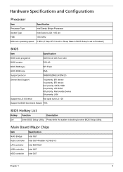
Hardware Specifications and Configurations Processor Item Specification Processor Type Intel Sandy Bridge Processor Socket Type Intel Socket LGA 1155 pin FSB 1333 MHz Minimum operating speed 0 MHz (If Stop CPU Clock in Sleep State in BIOS Setup is set to Enabled.) BIOS Item Specification BIOS code programer AMI Kernel with Acer skin BIOS version P02-A0 BIOS ROM type SPI Flash BIOS ROM size 8Mb Support protocol SMBIOS(DMI)2.4/DMI2.0 Device Boot Support 1st priority: EFI device 1st priority: EFI device 2nd priority: SATA HDD 3rd priority: CD-ROM 4th...
Hardware Specifications and Configurations Processor Item Specification Processor Type Intel Sandy Bridge Processor Socket Type Intel Socket LGA 1155 pin FSB 1333 MHz Minimum operating speed 0 MHz (If Stop CPU Clock in Sleep State in BIOS Setup is set to Enabled.) BIOS Item Specification BIOS code programer AMI Kernel with Acer skin BIOS version P02-A0 BIOS ROM type SPI Flash BIOS ROM size 8Mb Support protocol SMBIOS(DMI)2.4/DMI2.0 Device Boot Support 1st priority: EFI device 1st priority: EFI device 2nd priority: SATA HDD 3rd priority: CD-ROM 4th...
Acer Veriton M6618G Desktop Service Guide
Page 18
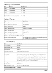
... jack Specification Intel Q67 ALC662 codec 5.1 Enable/disable by BIOS Setup Stereo Sound Blaster Pro/16 compatible Mixed digital and analog high performance chip Enhanced stereo full duplex operation High performance audio accelerator and AC'97 support Full native DOS games compatibility Virtual FM enhances audio experience through real-time FM-to error correction code (ECC) feature No Memory module combinations You can install memory...
... jack Specification Intel Q67 ALC662 codec 5.1 Enable/disable by BIOS Setup Stereo Sound Blaster Pro/16 compatible Mixed digital and analog high performance chip Enhanced stereo full duplex operation High performance audio accelerator and AC'97 support Full native DOS games compatibility Virtual FM enhances audio experience through real-time FM-to error correction code (ECC) feature No Memory module combinations You can install memory...
Acer Veriton M6618G Desktop Service Guide
Page 19
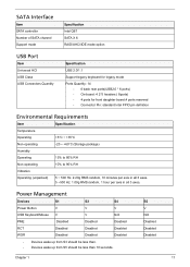
... Power Button V V V USB Keyboard/Mouse V V N/A PME Disabled Disabled Disabled RCT Disabled Disabled Disabled WOR Disabled Disabled Disabled • Devices wake up from S3 should be less than. • Devices wake up from S5 should be less than 10 seconds. SATA Interface Item SATA controller Number of SATA channel Support mode Specification Intel Q67 SATA X 6 RAID/AHCI/IDE mode option USB Port Item Universal HCI USB Class USB Connectors Quantity Specification USB 2.0/1.1 Support legacy keyboard for legacy mode Ports Quantity: 14 • 6 back rear ports(USB2.0 * 6 ports...
... Power Button V V V USB Keyboard/Mouse V V N/A PME Disabled Disabled Disabled RCT Disabled Disabled Disabled WOR Disabled Disabled Disabled • Devices wake up from S3 should be less than. • Devices wake up from S5 should be less than 10 seconds. SATA Interface Item SATA controller Number of SATA channel Support mode Specification Intel Q67 SATA X 6 RAID/AHCI/IDE mode option USB Port Item Universal HCI USB Class USB Connectors Quantity Specification USB 2.0/1.1 Support legacy keyboard for legacy mode Ports Quantity: 14 • 6 back rear ports(USB2.0 * 6 ports...
Acer Veriton M6618G Desktop Service Guide
Page 21
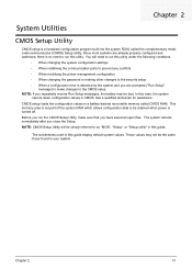
... no need to run this utility. The system reboots immediately after you have saved all open files. The screenshots used in this case, the system cannot retain configuration values in CMOS. Chapter 2 System Utilities CMOS Setup Utility CMOS setup is not part of the system RAM which allows configuration data to be simply referred to as "BIOS", "Setup", or "Setup utility" in this guide. This memory area is a hardware configuration program built into the system ROM, called CMOS RAM...
... no need to run this utility. The system reboots immediately after you have saved all open files. The screenshots used in this case, the system cannot retain configuration values in CMOS. Chapter 2 System Utilities CMOS Setup Utility CMOS setup is not part of the system RAM which allows configuration data to be simply referred to as "BIOS", "Setup", or "Setup utility" in this guide. This memory area is a hardware configuration program built into the system ROM, called CMOS RAM...
Acer Veriton M6618G Desktop Service Guide
Page 23
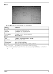
.... Date when the BIOS setup utility was built Type of this system. In the descriptive table following main setup categories. Core speed of the menu screenshots, settings in boldface are the default and suggested settings. Serial number of the system. Set the system time following the weekday-month-day-year format. Main The Setup Main menu includes the following each of the CPU installed on the system...
.... Date when the BIOS setup utility was built Type of this system. In the descriptive table following main setup categories. Core speed of the menu screenshots, settings in boldface are the default and suggested settings. Serial number of the system. Set the system time following the weekday-month-day-year format. Main The Setup Main menu includes the following each of the CPU installed on the system...
Acer Veriton M6618G Desktop Service Guide
Page 30
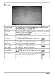
... Operation TPM Enabled Status TPM Active Status TPM Owner Status Removable Device Boot Chassis Open Warning Chassis Open Description Option This item indicates whether a supervisor password has been set . This item indicates whether a HDD password has been set . You can select this option and press to change user password. This item is opened . Enabled Disabled This item displays the TPM status to support TPM (Trusted Platform Module) funtion. This item enables or disables support the boot from USB...
... Operation TPM Enabled Status TPM Active Status TPM Owner Status Removable Device Boot Chassis Open Warning Chassis Open Description Option This item indicates whether a supervisor password has been set . This item indicates whether a HDD password has been set . You can select this option and press to change user password. This item is opened . Enabled Disabled This item displays the TPM status to support TPM (Trusted Platform Module) funtion. This item enables or disables support the boot from USB...
Acer Veriton M6618G Desktop Service Guide
Page 31
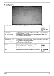
...No Errors All Errors Chapter 2 23 Press Enter to access the Optical Disk Drive Priority submenu and specify the boot device priority sequence from the available devices. Enabled Disabled When enabled, the BIOS splash screen displays during startup. Press Enter to access the Hard Disk Drive Priority submenu and specify the boot device priority sequence from available network drives. Boot Options 1st/2nd/3rd/4th/5th Boot Device EFI Device Priority Hard Disk Drive Priority Optical Disk Drive Priority Removable Device Priority Network Device Priority Fast Boot Quiet Boot Halt...
...No Errors All Errors Chapter 2 23 Press Enter to access the Optical Disk Drive Priority submenu and specify the boot device priority sequence from the available devices. Enabled Disabled When enabled, the BIOS splash screen displays during startup. Press Enter to access the Hard Disk Drive Priority submenu and specify the boot device priority sequence from available network drives. Boot Options 1st/2nd/3rd/4th/5th Boot Device EFI Device Priority Hard Disk Drive Priority Optical Disk Drive Priority Removable Device Priority Network Device Priority Fast Boot Quiet Boot Halt...
Acer Veriton M6618G Desktop Service Guide
Page 89
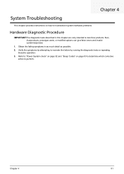
... "Power System check" on page 82 and "Beep Codes" on how to troubleshoot system hardware problems. Hardware Diagnostic Procedure IMPORTANT:The diagnostic tests described in as much detail as possible. 2. Verify the symptoms by attempting to recreate the failure by running the diagnostic tests or repeating thesame operation. 3. Chapter 4 81 NonAcerproducts, prototype cards, or modified options can give false errors and invalid systemresponses. 1. Chapter 4 System Troubleshooting This chapter provides instructions...
... "Power System check" on page 82 and "Beep Codes" on how to troubleshoot system hardware problems. Hardware Diagnostic Procedure IMPORTANT:The diagnostic tests described in as much detail as possible. 2. Verify the symptoms by attempting to recreate the failure by running the diagnostic tests or repeating thesame operation. 3. Chapter 4 81 NonAcerproducts, prototype cards, or modified options can give false errors and invalid systemresponses. 1. Chapter 4 System Troubleshooting This chapter provides instructions...
Acer Veriton M6618G Desktop Service Guide
Page 92
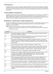
... add-in PMM. Both key sequence and OEM specific method is checked to determine if BIOSrecovery is done. The Bootblock-Runtime interface module is moved to system memory and control is given to it . Early Boot Strap Processor (BSP) initialization like microcode update, frequency and other components before memory detection. If BIOS recovery is enabled at this point if needed for future use in PCI devices...
... add-in PMM. Both key sequence and OEM specific method is checked to determine if BIOSrecovery is done. The Bootblock-Runtime interface module is moved to system memory and control is given to it . Early Boot Strap Processor (BSP) initialization like microcode update, frequency and other components before memory detection. If BIOS recovery is enabled at this point if needed for future use in PCI devices...
Acer Veriton M6618G Desktop Service Guide
Page 94
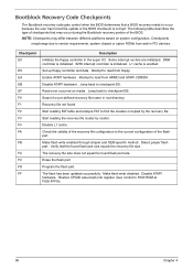
... I/O. Check the validity of the flash part. Jump back to the current configuration of the recovery file configuration to checkpoint EB. Make flash write enabled through chipset and OEM specific method. Restore CPUID value back into register. DMA controller is initialized. 8259 interrupt controller is enabled. Disable L1 cache. Start reading FAT table and analyze FAT to read from add-in PCI devices. Checkpoint E0 E9 EA EB...
... I/O. Check the validity of the flash part. Jump back to the current configuration of the recovery file configuration to checkpoint EB. Make flash write enabled through chipset and OEM specific method. Restore CPUID value back into register. DMA controller is initialized. 8259 interrupt controller is enabled. Disable L1 cache. Start reading FAT table and analyze FAT to read from add-in PCI devices. Checkpoint E0 E9 EA EB...
Acer Veriton M6618G Desktop Service Guide
Page 95
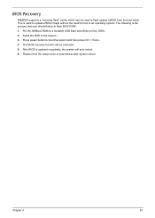
... user should follow to flash BIOS ROM. 1. Please enter the setup menu to a bootable USB flash drive(Disk on Key, DOK). 2. This is used to an operating system. Put the AMIBoot.ROM to load default after system reboot. The BIOS recovery function will auto reboot. 6. Install the DOK to boot the system and then press Ctrl + Home. 4. The following is updated completely, the system will be used to update a BIOS image without the need to boot to flash update a BIOS from the boot...
... user should follow to flash BIOS ROM. 1. Please enter the setup menu to a bootable USB flash drive(Disk on Key, DOK). 2. This is used to an operating system. Put the AMIBoot.ROM to load default after system reboot. The BIOS recovery function will auto reboot. 6. Install the DOK to boot the system and then press Ctrl + Home. 4. The following is updated completely, the system will be used to update a BIOS image without the need to boot to flash update a BIOS from the boot...

Acer Veriton M6618G Desktop Service Guide
Page 97
... port header Opened Chassis detect header Serial ATA 3.0 Gb/s connectors (Red color)(compatible with SATA 2.0) Serial ATA 3.0 Gb/s connectors (Red color) or Serial ATA 2.0 connectors(Black color) Serial ATA 2.0 Gb/s connectors (Black color) BIOS write protecting jumper Front panel switch/LED header For factory use only Front panel USB headers Clear CMOS jumper One button recovery jumper ME Disable Header Front panel USB header(1*4pin for card reader) SPDIF out header Speaker header Front panel audio header 32-bit add-on card slot PCI Express x1 slots PCI Express x16 slot System cooling fan...
... port header Opened Chassis detect header Serial ATA 3.0 Gb/s connectors (Red color)(compatible with SATA 2.0) Serial ATA 3.0 Gb/s connectors (Red color) or Serial ATA 2.0 connectors(Black color) Serial ATA 2.0 Gb/s connectors (Black color) BIOS write protecting jumper Front panel switch/LED header For factory use only Front panel USB headers Clear CMOS jumper One button recovery jumper ME Disable Header Front panel USB header(1*4pin for card reader) SPDIF out header Speaker header Front panel audio header 32-bit add-on card slot PCI Express x1 slots PCI Express x16 slot System cooling fan...
Acer Veriton M6618G Desktop Service Guide
Page 98
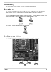
... illustration shows a 3-pin jumper. Pins1 and 2 are numbered. When setting the jumpers, ensure that the jumper caps are Placed on just one pin are SHORT. Jumper Setting The section explains how to set jumper for correct configuration of the motherboard jumpers. Setting Jumper Use the motherboard jumpers to set system configuration options. Jumpers with more Than one pin,the jumper is OPEN. Checking Jumper Settings The following illustration shows the location of the mainboard. If you remove the jumpercap, or...
... illustration shows a 3-pin jumper. Pins1 and 2 are numbered. When setting the jumpers, ensure that the jumper caps are Placed on just one pin are SHORT. Jumper Setting The section explains how to set jumper for correct configuration of the motherboard jumpers. Setting Jumper Use the motherboard jumpers to set system configuration options. Jumpers with more Than one pin,the jumper is OPEN. Checking Jumper Settings The following illustration shows the location of the mainboard. If you remove the jumpercap, or...
Acer Veriton M6618G Desktop Service Guide
Page 125
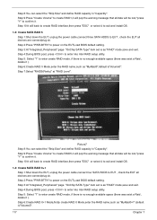
... "ESC" or select 4 to exit and install OS. 1-4: Create SATA RAID 0+1 Step 1:Shut down the EUT, unplug the power cable,connect three SATA HDDS to confirm it ). Step 2:Press "PWR-BTTN" to enter into Intel RAID setup utility. Step 4:During BIOS post, press to power on the EUT,Load BIOS default setting . Step 6:Create RAID 5 Mode,enter the RAID name,such as "MyRaid0+1",default is as "RAID" mode,save and exit. Picture7 Step 8:You...
... "ESC" or select 4 to exit and install OS. 1-4: Create SATA RAID 0+1 Step 1:Shut down the EUT, unplug the power cable,connect three SATA HDDS to confirm it ). Step 2:Press "PWR-BTTN" to enter into Intel RAID setup utility. Step 4:During BIOS post, press to power on the EUT,Load BIOS default setting . Step 6:Create RAID 5 Mode,enter the RAID name,such as "MyRaid0+1",default is as "RAID" mode,save and exit. Picture7 Step 8:You...


