Service Guide
Page 5
... in the printed Service Guide. If, for whatever reason, a part number change is made, it supports, please read the following general information. 1. For ACER-AUTHORIZED SERVICE PROVIDERS, your regional office MAY have a DIFFERENT part number code to provide you with all technical information relating to extend the functionality of customer machines. Please note WHEN ORDERING FRU PARTS, that you with further technical details. 2. add-on your...
... in the printed Service Guide. If, for whatever reason, a part number change is made, it supports, please read the following general information. 1. For ACER-AUTHORIZED SERVICE PROVIDERS, your regional office MAY have a DIFFERENT part number code to provide you with all technical information relating to extend the functionality of customer machines. Please note WHEN ORDERING FRU PARTS, that you with further technical details. 2. add-on your...
Service Guide
Page 6
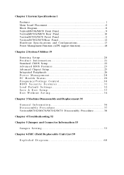
... board Placement 6 Block Diagram...8 VeritonM670G/M670 Front Panel 9 VeritonM670G/M670 Rear Panel 10 VeritonS670G/S670 Front Panel 11 VeritonS670G/S670Rear Panel 12 Hardware Specifications and Configurations 13 Power Management Function (ACPI support function 18 Chapter 2 System Utilities 19 Entering Setup 20 Product Information 21 Standard CMOS Setup 22 Advanced BIOS Features 23 Advanced Chipset Setup 25 Integrated Peripherals 26 Power Management 28 PC Health Status 29 Frequency/Voltage Control 30 BIOS Security Features 31 Load Default Settings 32...
... board Placement 6 Block Diagram...8 VeritonM670G/M670 Front Panel 9 VeritonM670G/M670 Rear Panel 10 VeritonS670G/S670 Front Panel 11 VeritonS670G/S670Rear Panel 12 Hardware Specifications and Configurations 13 Power Management Function (ACPI support function 18 Chapter 2 System Utilities 19 Entering Setup 20 Product Information 21 Standard CMOS Setup 22 Advanced BIOS Features 23 Advanced Chipset Setup 25 Integrated Peripherals 26 Power Management 28 PC Health Status 29 Frequency/Voltage Control 30 BIOS Security Features 31 Load Default Settings 32...
Service Guide
Page 8
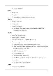
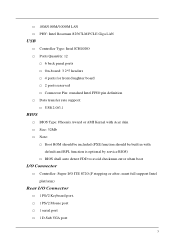
... Type support: … HDD/CD-ROM/CD-RW/DVD-ROM/DVD-RW/DVD+RW/DVD Dual/DVD SuperMulti Plus/ Audio … Audio Type: HD audio codec … Audio Channel: 7.1 channel … Audio Controller /Codec: ALC888S HD codec 7.1 … Connectors support: … Rear 6 jack follow HD audio definition, example as below … Audio jacks color coding: should meet Microsoft Windows Logo Program Device Requirements: Audio-0002 … 1 S/PDIF-out header (1*4) … 1 AUX-In header (1*4) … 1 front panel audio header (2*5) … Add...
... Type support: … HDD/CD-ROM/CD-RW/DVD-ROM/DVD-RW/DVD+RW/DVD Dual/DVD SuperMulti Plus/ Audio … Audio Type: HD audio codec … Audio Channel: 7.1 channel … Audio Controller /Codec: ALC888S HD codec 7.1 … Connectors support: … Rear 6 jack follow HD audio definition, example as below … Audio jacks color coding: should meet Microsoft Windows Logo Program Device Requirements: Audio-0002 … 1 S/PDIF-out header (1*4) … 1 AUX-In header (1*4) … 1 front panel audio header (2*5) … Add...
Service Guide
Page 9
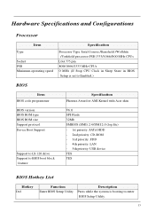
... transfer rate support: … USB 2.0/1.1 BIOS … BIOS Type: Phoenix Award or AMI Kernel with Acer skin … Size: 32Mb … Note: … Boot ROM should be included (PXE function should be built in with default and RPL function is optional by service BIOS) … BIOS shall auto detect FDD to avoid checksum error when boot I/O Connector … Controller: Super I /O Connector … 1 PS/2 Keyboard port, … 1 PS/2 Mouse port … 1 serial port … 1 D-Sub VGA port 3
... transfer rate support: … USB 2.0/1.1 BIOS … BIOS Type: Phoenix Award or AMI Kernel with Acer skin … Size: 32Mb … Note: … Boot ROM should be included (PXE function should be built in with default and RPL function is optional by service BIOS) … BIOS shall auto detect FDD to avoid checksum error when boot I/O Connector … Controller: Super I /O Connector … 1 PS/2 Keyboard port, … 1 PS/2 Mouse port … 1 serial port … 1 D-Sub VGA port 3
Service Guide
Page 10
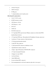
...2 PCI slot … 1 FDD slot … 6 SATAII connectors … 3 2*5 pin Intel FPIO specification USB pin connectors (follow Intel FPIO standard Specification) … 1 2*5 pin Intel FPIO spec. Microphone In/ Headphone Out pin connectors … 1 serial port 2*5 pin connector (2nd serial port) … 1 2*4 pin internal speaker header … 1 4 pin CPU Fan connector … 1 3 pin System FAN connector with linear circuit … 1 2pin Intrusion Alarm connector … 1 24pin + 4pin ATX interface PS3/PS2 SPS connector … 1 2*7 pin front panel IO header … 1 Jumper for clear CMOS …...
...2 PCI slot … 1 FDD slot … 6 SATAII connectors … 3 2*5 pin Intel FPIO specification USB pin connectors (follow Intel FPIO standard Specification) … 1 2*5 pin Intel FPIO spec. Microphone In/ Headphone Out pin connectors … 1 serial port 2*5 pin connector (2nd serial port) … 1 2*4 pin internal speaker header … 1 4 pin CPU Fan connector … 1 3 pin System FAN connector with linear circuit … 1 2pin Intrusion Alarm connector … 1 24pin + 4pin ATX interface PS3/PS2 SPS connector … 1 2*7 pin front panel IO header … 1 Jumper for clear CMOS …...
Service Guide
Page 11
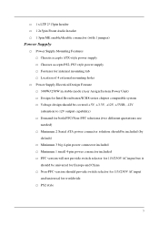
...; 1 2x5pin Front Audio header … 1 3pin ME enable/disable connector (with 1 jumper) Power Supply … Power Supply Mounting Features … Chassis accepts ATX-style power supply … Chasses accepts PS2, PS3 style power supply … Features for internal mounting tab … Location of 4 external mounting holes … Power Supply Electrical Design Feature … 300W/250W in stable mode (Acer Assign System Power Unit) … Design for Intel Broadwater/ICH8 series chipset compatible...
...; 1 2x5pin Front Audio header … 1 3pin ME enable/disable connector (with 1 jumper) Power Supply … Power Supply Mounting Features … Chassis accepts ATX-style power supply … Chasses accepts PS2, PS3 style power supply … Features for internal mounting tab … Location of 4 external mounting holes … Power Supply Electrical Design Feature … 300W/250W in stable mode (Acer Assign System Power Unit) … Design for Intel Broadwater/ICH8 series chipset compatible...
Service Guide
Page 16
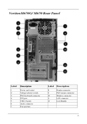
VeritonM670G/ M670 Rear Panel Label 1 2 3 4 5 6 7 Description Power card socket Voltage selector switch PS/2 keyboard connector DVI port USB 2.0 ports Audio connector Fan aperture Label 8 9 10 11 12 Description Printer connector PS/2 mouse connector Monitor connector LAN connector Lock Handle 10
VeritonM670G/ M670 Rear Panel Label 1 2 3 4 5 6 7 Description Power card socket Voltage selector switch PS/2 keyboard connector DVI port USB 2.0 ports Audio connector Fan aperture Label 8 9 10 11 12 Description Printer connector PS/2 mouse connector Monitor connector LAN connector Lock Handle 10
Service Guide
Page 19
... CPU Clock in Sleep State in BIOS Setup is set to Enabled.) BIOS Item BIOS code programmer Specification Phoenix Award or AMI Kernel with Acer skin BIOS version BIOS ROM type BIOS ROM size Support protocol Device Boot Support Support to LS-120 drive Support to BIOS boot block feature V6.0 SPI Flash 32Mb SMBIOS (DMI) 2.4/DMI 2.0 (log file) - 1st priority: SATA HDD - 2nd priority: CD-ROM - 3rd priority: FDD - 4th priority: LAN - 5th priority: USB device YES YES BIOS Hotkey List Hotkey Del Function Enter BIOS Setup Utility...
... CPU Clock in Sleep State in BIOS Setup is set to Enabled.) BIOS Item BIOS code programmer Specification Phoenix Award or AMI Kernel with Acer skin BIOS version BIOS ROM type BIOS ROM size Support protocol Device Boot Support Support to LS-120 drive Support to BIOS boot block feature V6.0 SPI Flash 32Mb SMBIOS (DMI) 2.4/DMI 2.0 (log file) - 1st priority: SATA HDD - 2nd priority: CD-ROM - 3rd priority: FDD - 4th priority: LAN - 5th priority: USB device YES YES BIOS Hotkey List Hotkey Del Function Enter BIOS Setup Utility...
Service Guide
Page 20
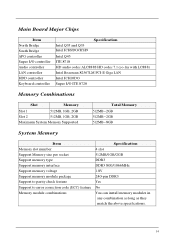
... I/O controller Audio controller LAN controller HDD controller Keyboard controller Intel Q35 and Q33 Intel ICH9DO/ICH9 Specification Intel Q45 ITE 8718 HD audio codec ALC888S HD codec 7.1 (co-lay with LC888) Intel Boazman 82567LM PCI-E Giga LAN Intel ICH10DO Super I/O ITE 8720 Memory Combinations Slot Memory Slot 1 512MB, 1GB, 2GB Slot 2 512MB, 1GB, 2GB Maximum System Memory Supported Total Memory 512MB~2GB 512MB~2GB 512MB~8GB System Memory Item Memory slot number Support Memory size per socket Support memory type Support memory...
... I/O controller Audio controller LAN controller HDD controller Keyboard controller Intel Q35 and Q33 Intel ICH9DO/ICH9 Specification Intel Q45 ITE 8718 HD audio codec ALC888S HD codec 7.1 (co-lay with LC888) Intel Boazman 82567LM PCI-E Giga LAN Intel ICH10DO Super I/O ITE 8720 Memory Combinations Slot Memory Slot 1 512MB, 1GB, 2GB Slot 2 512MB, 1GB, 2GB Maximum System Memory Supported Total Memory 512MB~2GB 512MB~2GB 512MB~8GB System Memory Item Memory slot number Support Memory size per socket Support memory type Support memory...
Service Guide
Page 21
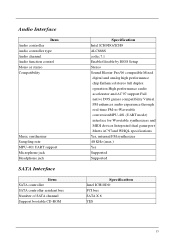
Audio Interface Item Audio controller Audio controller type Audio channel Audio function control Mono or stereo Compatibility Music synthesizer Sampling rate MPU-401 UART support Microphone jack Headphone jack SATA Interface Item SATA controller SATA controller resident bus Number of SATA channel Support bootable CD-ROM Specification Intel ICH9DO/ICH9 ALC888S codec 7.1 Enable/disable by BIOS Setup Stereo Sound Blaster Pro/16 compatible Mixed digital and analog high performance chip Enhanced stereo full duplex operation High performance...
Audio Interface Item Audio controller Audio controller type Audio channel Audio function control Mono or stereo Compatibility Music synthesizer Sampling rate MPU-401 UART support Microphone jack Headphone jack SATA Interface Item SATA controller SATA controller resident bus Number of SATA channel Support bootable CD-ROM Specification Intel ICH9DO/ICH9 ALC888S codec 7.1 Enable/disable by BIOS Setup Stereo Sound Blaster Pro/16 compatible Mixed digital and analog high performance chip Enhanced stereo full duplex operation High performance...
Service Guide
Page 22
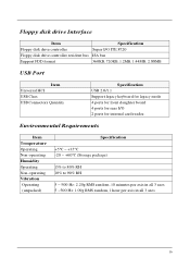
... minutes per axis in all 3 axes 5 ~500 Hz: 1.09g RMS random, 1 hour per axis in all 3 axes 16 Floppy disk drive Interface Item Specification Floppy disk drive controller Super I/O ITE 8720 Floppy disk drive controller resident bus ISA bus Support FDD format 360KB, 720KB, 1.2MB, 1.44MB, 2.88MB USB Port Item Universal HCI USB Class USB Connectors Quantity Specification USB 2.0/1.1 Support legacy keyboard for legacy mode 4 ports for front daughter board 4 ports for rear I/O 2 ports for internal card reader.
... minutes per axis in all 3 axes 5 ~500 Hz: 1.09g RMS random, 1 hour per axis in all 3 axes 16 Floppy disk drive Interface Item Specification Floppy disk drive controller Super I/O ITE 8720 Floppy disk drive controller resident bus ISA bus Support FDD format 360KB, 720KB, 1.2MB, 1.44MB, 2.88MB USB Port Item Universal HCI USB Class USB Connectors Quantity Specification USB 2.0/1.1 Support legacy keyboard for legacy mode 4 ports for front daughter board 4 ports for rear I/O 2 ports for internal card reader.

Service Guide
Page 25
... this case, the system cannot retain configuration values in CMOS. The Setup program loads configuration values into the battery-backed nonvolatile memory called CMOS RAM. This memory area is no need to run Setup, make sure that you repeatedly receive Run Setup messages, the battery may be bad/flat. Before you run Setup when starting the computer unless you exit Setup. 19 The system reboots immediately after you get a Run Setup message. Chapter 2 System Utilities...
... this case, the system cannot retain configuration values in CMOS. The Setup program loads configuration values into the battery-backed nonvolatile memory called CMOS RAM. This memory area is no need to run Setup, make sure that you repeatedly receive Run Setup messages, the battery may be bad/flat. Before you run Setup when starting the computer unless you exit Setup. 19 The system reboots immediately after you get a Run Setup message. Chapter 2 System Utilities...
Service Guide
Page 26
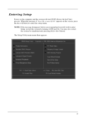
Entering Setup Power on the screen, press the key of "Press DEL to enter SETUP" appears on the computer and the system will start POST (Power On Self Test) process. When the message of [Delete] to enter Setup, restart the system by simultaneously pressing [Ctrl+ Alt+ Delete]. NOTE: If the message disappears before you respond and you still wish to enter the setup menu. The Setup Utility main menu then appears: 20 You may also restart the system by turning it OFF and On.
Entering Setup Power on the screen, press the key of "Press DEL to enter SETUP" appears on the computer and the system will start POST (Power On Self Test) process. When the message of [Delete] to enter Setup, restart the system by simultaneously pressing [Ctrl+ Alt+ Delete]. NOTE: If the message disappears before you respond and you still wish to enter the setup menu. The Setup Utility main menu then appears: 20 You may also restart the system by turning it OFF and On.

Service Guide
Page 27
... setup Exit Without Saving Abandon all CMOS value changes and exit setup 21 It allows you to limit access to the System Load Optimized Defaults Save & Exit Setup Load Optimized Settings Default Settings indicates the value of Green function features This setup page is the System auto detect Temperature, voltage, and fan speed This setup page is the System Frequency/Voltage setup BIOS Security Features Change, set or disable password...
... setup Exit Without Saving Abandon all CMOS value changes and exit setup 21 It allows you to limit access to the System Load Optimized Defaults Save & Exit Setup Load Optimized Settings Default Settings indicates the value of Green function features This setup page is the System auto detect Temperature, voltage, and fan speed This setup page is the System Frequency/Voltage setup BIOS Security Features Change, set or disable password...
Service Guide
Page 29
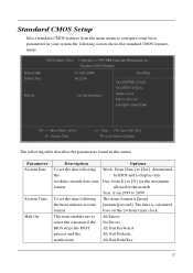
... item enables use to [31] (or the maximum format allowed in the month. Parameter System Date System Time Halt On Description Options To set the time following The items format is [hour] the hour-minute-second [minute][second]. Standard CMOS Setup Select standard CMOS features from the main menu to configure some basic parameters in your system the following screen...
... item enables use to [31] (or the maximum format allowed in the month. Parameter System Date System Time Halt On Description Options To set the time following The items format is [hour] the hour-minute-second [minute][second]. Standard CMOS Setup Select standard CMOS features from the main menu to configure some basic parameters in your system the following screen...
Service Guide
Page 30
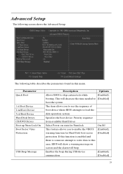
... of boot device where BIOS attempts to load the disk operation system. Specifies the boot device. If this function is enabled and there is someone attempt to write data to skip certain tests while [Enabled], booting. Parameter Quick Boot 1 st Boot Device 2 nd Boot Device 3 rd Boot Device Hard Disk Drives CD/DVD Drives Boot up Num-Lock On Boot Sector Virus Protection USB Beep Message Description Options Allows BIOS to this menu. Advanced Setup The following screen shows the Advanced Setup: The...
... of boot device where BIOS attempts to load the disk operation system. Specifies the boot device. If this function is enabled and there is someone attempt to write data to skip certain tests while [Enabled], booting. Parameter Quick Boot 1 st Boot Device 2 nd Boot Device 3 rd Boot Device Hard Disk Drives CD/DVD Drives Boot up Num-Lock On Boot Sector Virus Protection USB Beep Message Description Options Allows BIOS to this menu. Advanced Setup The following screen shows the Advanced Setup: The...
Service Guide
Page 31
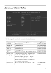
... TXT Intel AMT ASF Memory Hole Remapping Primary Video Description For Intel platform For Intel platform For Intel platform For Intel platform For Intel platform For Veriton series with vPro or DASH solution You can reserve this area of system memory for Auto : PCIE -> Onboard -> PCI Options Disabled/Enabled Disabled/Enabled Disabled/Enabled Disabled/Enabled Disabled/Enabled Disabled/Enabled Disabled/Enabled Auto/PCIE/Onbo ard/PCI 25 Advanced Chipset Setup The following table...
... TXT Intel AMT ASF Memory Hole Remapping Primary Video Description For Intel platform For Intel platform For Intel platform For Intel platform For Intel platform For Veriton series with vPro or DASH solution You can reserve this area of system memory for Auto : PCIE -> Onboard -> PCI Options Disabled/Enabled Disabled/Enabled Disabled/Enabled Disabled/Enabled Disabled/Enabled Disabled/Enabled Disabled/Enabled Auto/PCIE/Onbo ard/PCI 25 Advanced Chipset Setup The following table...
Service Guide
Page 33
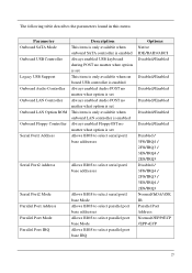
... in this menu. Parameter Onboard SATA Mode Onboard USB Controller Legacy USB Support Onboard Audio Controller Onboard LAN Controller Onboard LAN Option ROM Onboard Floppy Controller Serial Port1 Address Description This item is only available when onboard SATA controller is enabled Always enabled USB keyboard during POST no matter what option is set This item is only available when on board USB controller is enabled Always enabled Audio POST no matter what option is set Always enabled Audio POST no matter what option is set This...
... in this menu. Parameter Onboard SATA Mode Onboard USB Controller Legacy USB Support Onboard Audio Controller Onboard LAN Controller Onboard LAN Option ROM Onboard Floppy Controller Serial Port1 Address Description This item is only available when onboard SATA controller is enabled Always enabled USB keyboard during POST no matter what option is set This item is only available when on board USB controller is enabled Always enabled Audio POST no matter what option is set Always enabled Audio POST no matter what option is set This...
Service Guide
Page 34
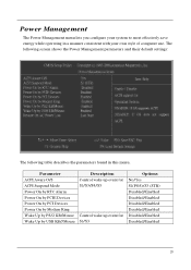
... PCIE Devices Power On by PCI Devices Power On by Modem Ring Wake Up by PS/2 KB/Mouse Wake Up by USB KB//Mouse Description Control wake up event for S1/S3/S4/S5 Control wake up event for S1/S3 Options No/Yes S1(POS)/S3 (STR) Disabled/Enabled Disabled/Enabled Disabled/Enabled Disabled/Enabled Disabled/Enabled Disabled/Enabled 28 Power Management The Power Management menu lets you configure your own style of computer use. The following screen shows the Power Management parameters and their default settings: The...
... PCIE Devices Power On by PCI Devices Power On by Modem Ring Wake Up by PS/2 KB/Mouse Wake Up by USB KB//Mouse Description Control wake up event for S1/S3/S4/S5 Control wake up event for S1/S3 Options No/Yes S1(POS)/S3 (STR) Disabled/Enabled Disabled/Enabled Disabled/Enabled Disabled/Enabled Disabled/Enabled Disabled/Enabled 28 Power Management The Power Management menu lets you configure your own style of computer use. The following screen shows the Power Management parameters and their default settings: The...
Service Guide
Page 37
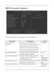
... Removable Device Boot Chassis Opened Warning Description This item is only available when supervisor password is yes Control system booting from floppy, USB handy drive, or memory card For Veriton series electron lock, Options Press Enter No/Yes Don't Change/Disab led/Enabled Disabled/Ena bled Disabled/Ena bled/Clear 31 All setup items will be view-only except user password item when login with user password This item is only available when TPM controller/module is installed...
... Removable Device Boot Chassis Opened Warning Description This item is only available when supervisor password is yes Control system booting from floppy, USB handy drive, or memory card For Veriton series electron lock, Options Press Enter No/Yes Don't Change/Disab led/Enabled Disabled/Ena bled Disabled/Ena bled/Clear 31 All setup items will be view-only except user password item when login with user password This item is only available when TPM controller/module is installed...


