
Service Guide
Page 6
...4 8 8 G / S 4 8 0 Front Panel 7 Ve r i t o n S 4 8 0 G / S 4 8 8 G / S 4 8 0 Rear Panel 8 Hardware Specifications and Configurations 9 Power Management Function (ACPI support function 16 Chapter 2 System Utilities 17 Entering Setup 18 Product Information 20 Standard CMOS Features 21 Advanced BIOS Features 23 Advanced Chipset Features 24 Integrated Peripherals 25 Power Management Setup 27 PC Health Status 28 Frequency/Voltage Control 29 BIOS Security Features 30 Load Default Settings 31 Save & Exit Setup 32 Exit Without Saving 33 Chapter 3 Machine Disassembly and Replacement 34...
...4 8 8 G / S 4 8 0 Front Panel 7 Ve r i t o n S 4 8 0 G / S 4 8 8 G / S 4 8 0 Rear Panel 8 Hardware Specifications and Configurations 9 Power Management Function (ACPI support function 16 Chapter 2 System Utilities 17 Entering Setup 18 Product Information 20 Standard CMOS Features 21 Advanced BIOS Features 23 Advanced Chipset Features 24 Integrated Peripherals 25 Power Management Setup 27 PC Health Status 28 Frequency/Voltage Control 29 BIOS Security Features 30 Load Default Settings 31 Save & Exit Setup 32 Exit Without Saving 33 Chapter 3 Machine Disassembly and Replacement 34...
Service Guide
Page 8
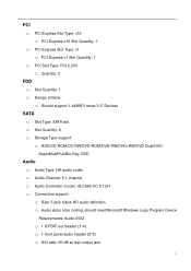
... support 1.44MB/3 mode 3.5" Devices SATA … Slot Type: SATA slot … Slot Quantity: 6 … Storage Type support: … HDD/CD-ROM/CD-RW/DVD-ROM/DVD-RW/DVD+RW/DVD Dual/DVD SuperMultiPlus/Blu-Ray ODD Audio … Audio Type: HD audio codec … Audio Channel: 5.1 channel … Audio Controller /Codec: ALC662-VC 5.1CH … Connectors support: … Rear 3 jack follow HD audio definition, … Audio jacks color coding: should meet Microsoft Windows Logo Program Device Requirements: Audio-0002 … 1 S/PDIF-out header (1*4) … 1 front panel audio header...
... support 1.44MB/3 mode 3.5" Devices SATA … Slot Type: SATA slot … Slot Quantity: 6 … Storage Type support: … HDD/CD-ROM/CD-RW/DVD-ROM/DVD-RW/DVD+RW/DVD Dual/DVD SuperMultiPlus/Blu-Ray ODD Audio … Audio Type: HD audio codec … Audio Channel: 5.1 channel … Audio Controller /Codec: ALC662-VC 5.1CH … Connectors support: … Rear 3 jack follow HD audio definition, … Audio jacks color coding: should meet Microsoft Windows Logo Program Device Requirements: Audio-0002 … 1 S/PDIF-out header (1*4) … 1 front panel audio header...
Service Guide
Page 9
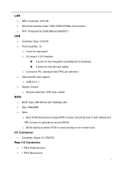
... Criteria: … Should meet Acer USB drop criteria BIOS … BIOS Type: AMI Kernel with Gateway skin … Size: 4Mb/8MB … Note: … Boot ROM should be included (PXE function should be built in with default and RPL function is optional by service BIOS) … BIOS shall auto detect FDD to avoid checksum error when boot I/O Connector … Controller: Super I/O ITE8720 Rear I/O Connector … 1 PS/2 Keyboard port, … 1 PS/2 Mouse port, 3
... Criteria: … Should meet Acer USB drop criteria BIOS … BIOS Type: AMI Kernel with Gateway skin … Size: 4Mb/8MB … Note: … Boot ROM should be included (PXE function should be built in with default and RPL function is optional by service BIOS) … BIOS shall auto detect FDD to avoid checksum error when boot I/O Connector … Controller: Super I/O ITE8720 Rear I/O Connector … 1 PS/2 Keyboard port, … 1 PS/2 Mouse port, 3
Service Guide
Page 10
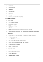
.../PS2 SPS connector … 1 2*7 pin front panel I/O header … 1 Jumper for clear CMOS … 1 2pin OBR header … 1 on board buzzer … 2 reserved 2pin GPIO connector … 1 2*10pin TPM header … 1 Serial port header (COM2) 4 Microphone In/ Headphone Out pin connectors … 1 SPDIF out header x2 … 1 4 pin CPU/SYS Fan connector … 1 3 pin System FAN connector with gfx card) … 3 2*5 pin Intel FPIO specification USB pin connectors (follow Intel FPIO standard Specification) … 1 2*5 pin Intel FPIO spec.
.../PS2 SPS connector … 1 2*7 pin front panel I/O header … 1 Jumper for clear CMOS … 1 2pin OBR header … 1 on board buzzer … 2 reserved 2pin GPIO connector … 1 2*10pin TPM header … 1 Serial port header (COM2) 4 Microphone In/ Headphone Out pin connectors … 1 SPDIF out header x2 … 1 4 pin CPU/SYS Fan connector … 1 3 pin System FAN connector with gfx card) … 3 2*5 pin Intel FPIO specification USB pin connectors (follow Intel FPIO standard Specification) … 1 2*5 pin Intel FPIO spec.
Service Guide
Page 13
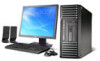
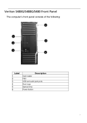
Veriton S480G/S488G/S480 Front Panel The computer's front panel consists of the following: 4 1 5 2 3 6 Label 1 2 3 4 5 6 Description Card reader FDD USB and audio jack ports Acer Logo Optical drive Power Button 7
Veriton S480G/S488G/S480 Front Panel The computer's front panel consists of the following: 4 1 5 2 3 6 Label 1 2 3 4 5 6 Description Card reader FDD USB and audio jack ports Acer Logo Optical drive Power Button 7
Service Guide
Page 15
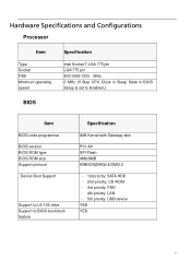
Hardware Specifications and Configurations Processor Item Type Socket FSB Minimum operating speed Specification Intel Socket T LGA 775 pin LGA 775 pin 800/1066/1333 MHz 0 MHz (If Stop CPU Clock in Sleep State in BIOS Setup is set to Enabled.) BIOS Item BIOS code programmer BIOS version BIOS ROM type BIOS ROM size Support protocol Device Boot Support Support to LS-120 drive Support to BIOS boot block feature Specification AMI Kernel with Gateway skin P01-A0 SPI Flash 4Mb/8MB SMBIOS(DMI)2.4/DMI2.0 - 1st priority: SATA HDD - 2nd...
Hardware Specifications and Configurations Processor Item Type Socket FSB Minimum operating speed Specification Intel Socket T LGA 775 pin LGA 775 pin 800/1066/1333 MHz 0 MHz (If Stop CPU Clock in Sleep State in BIOS Setup is set to Enabled.) BIOS Item BIOS code programmer BIOS version BIOS ROM type BIOS ROM size Support protocol Device Boot Support Support to LS-120 drive Support to BIOS boot block feature Specification AMI Kernel with Gateway skin P01-A0 SPI Flash 4Mb/8MB SMBIOS(DMI)2.4/DMI2.0 - 1st priority: SATA HDD - 2nd...
Service Guide
Page 16
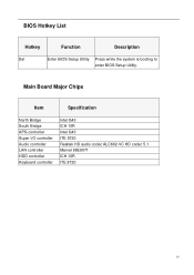
BIOS Hotkey List Hotkey Function Description Del Enter BIOS Setup Utility Press while the system is booting to enter BIOS Setup Utility. Main Board Major Chips Item Specification North Bridge South Bridge APG controller Super I/O controller Audio controller LAN controller HDD controller Keyboard controller Intel G43 ICH 10R Intel G43 ITE 8720 Realtek HD audio codec ALC662-VC HD codec 5.1 Marvel 88E8071 ICH 10R ITE 8720 10
BIOS Hotkey List Hotkey Function Description Del Enter BIOS Setup Utility Press while the system is booting to enter BIOS Setup Utility. Main Board Major Chips Item Specification North Bridge South Bridge APG controller Super I/O controller Audio controller LAN controller HDD controller Keyboard controller Intel G43 ICH 10R Intel G43 ITE 8720 Realtek HD audio codec ALC662-VC HD codec 5.1 Marvel 88E8071 ICH 10R ITE 8720 10
Service Guide
Page 22
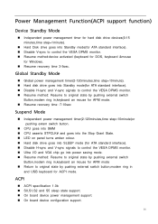
...; LED on panel turns amber colour. „ Hard disk drive goes into SLEEP mode (for ATA standard interface). „ Disable H-sync and V-sync signals to control the VESA DPMS monitor. „ Ultra I/O and VGA chip go into Standby mode(for ATA standard interface). „ Disable V-sync to original state by pushing external switch button,modem ring in and USB keyboard for Windows. „ Resume recovery time 3-5sec. Global Standby Mode „ Global power management...
...; LED on panel turns amber colour. „ Hard disk drive goes into SLEEP mode (for ATA standard interface). „ Disable H-sync and V-sync signals to control the VESA DPMS monitor. „ Ultra I/O and VGA chip go into Standby mode(for ATA standard interface). „ Disable V-sync to original state by pushing external switch button,modem ring in and USB keyboard for Windows. „ Resume recovery time 3-5sec. Global Standby Mode „ Global power management...
Service Guide
Page 24
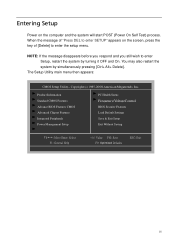
... setup menu. Entering Setup Power on the screen, press the key of "Press DEL to enter SETUP" appears on the computer and the system will start POST (Power On Self Test) process. When the message of [Delete] to enter Setup, restart the system by simultaneously pressing [Ctrl+ Alt+ Delete]. The Setup Utility main menu then appears: CMOS Setup Utility- Product Information Standard CMOS Features Advance BIOS Features CMOS Advanced Chipset Features Integrated Peripherals Power Management Setup...
... setup menu. Entering Setup Power on the screen, press the key of "Press DEL to enter SETUP" appears on the computer and the system will start POST (Power On Self Test) process. When the message of [Delete] to enter Setup, restart the system by simultaneously pressing [Ctrl+ Alt+ Delete]. The Setup Utility main menu then appears: CMOS Setup Utility- Product Information Standard CMOS Features Advance BIOS Features CMOS Advanced Chipset Features Integrated Peripherals Power Management Setup...
Service Guide
Page 26
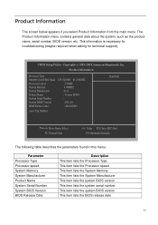
... :Acer : Veriton M480 : :P01-A0 : 04/10/2009 Asset Tag Number : Item Help KLIJ: Move Enter: Select F1: General Help +/-/: Value F10: Save ESC: Exit F9: Optimized Defaults The following table describes the parameters found in this menu: Parameter Processor Type Processor speed System Memory System Manufacturer Product Name System Serial Number System BIOS Version BIOS Release Date Description This item lists the Processor Type This item lists the Processor speed...
... :Acer : Veriton M480 : :P01-A0 : 04/10/2009 Asset Tag Number : Item Help KLIJ: Move Enter: Select F1: General Help +/-/: Value F10: Save ESC: Exit F9: Optimized Defaults The following table describes the parameters found in this menu: Parameter Processor Type Processor speed System Memory System Manufacturer Product Name System Serial Number System BIOS Version BIOS Release Date Description This item lists the Processor Type This item lists the Processor speed...

Service Guide
Page 29
...Options Quick Boot Allows BIOS to load 3 rd Boot Device the disk operation system. 4 th Boot Device Hard Disk Drive Specifies the boot device. Advanced BIOS Features Quick Boot Enabled Quiet Boot Enabled 1st Boot Device [Raid ST3320813AS] 2nd Boot Device [CD&DVD:P1-ATAPI DV] 3rd Boot Device [USB:Generic USB SD ] 4th Boot Device [LAN] Hard Disk Drive Priority [Press Enter] Optical Disk Device Priority [Press Enter] Removable Device Priority [Press Enter] Boot up Num-Lock On Select Power-on state for Numlock On,Off USB Beep Message Enables the beep during USB device...
...Options Quick Boot Allows BIOS to load 3 rd Boot Device the disk operation system. 4 th Boot Device Hard Disk Drive Specifies the boot device. Advanced BIOS Features Quick Boot Enabled Quiet Boot Enabled 1st Boot Device [Raid ST3320813AS] 2nd Boot Device [CD&DVD:P1-ATAPI DV] 3rd Boot Device [USB:Generic USB SD ] 4th Boot Device [LAN] Hard Disk Drive Priority [Press Enter] Optical Disk Device Priority [Press Enter] Removable Device Priority [Press Enter] Boot up Num-Lock On Select Power-on state for Numlock On,Off USB Beep Message Enables the beep during USB device...
Service Guide
Page 30
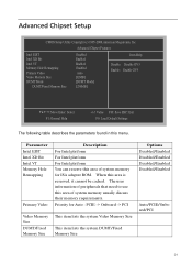
... For Intel platform For Intel platform You can reserve this area of system memory for Auto : PCIE -> Onboard -> PCI This item lists the system Video Memory Size This item lists the system DUMT/Fixed Memory Size Options Disabled/Enabled Disabled/Enabled Disabled/Enabled Disabled/Enabled Auto/PCIE/Onbo ard/PCI 24 Priority for ISA adapter ROM. The user information of peripherals that need to use this area of system memory usually discuss their...
... For Intel platform For Intel platform You can reserve this area of system memory for Auto : PCIE -> Onboard -> PCI This item lists the system Video Memory Size This item lists the system DUMT/Fixed Memory Size Options Disabled/Enabled Disabled/Enabled Disabled/Enabled Disabled/Enabled Auto/PCIE/Onbo ard/PCI 24 Priority for ISA adapter ROM. The user information of peripherals that need to use this area of system memory usually discuss their...
Service Guide
Page 32
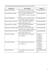
Parameter Onboard SATA Mode Onboard USB Controller Legacy USB Support Onboard Audio Controller Onboard LAN Controller Onboard LAN Option ROM Onboard Floppy Controller Serial Port1 Address Description This item is only available when onboard SATA controller is enabled Always enabled USB keyboard during POST no matter what option is set This item is only available when on board USB controller is enabled Always enabled Audio POST no matter what option is set Always enabled Audio POST no matter what option is set This item is only...
Parameter Onboard SATA Mode Onboard USB Controller Legacy USB Support Onboard Audio Controller Onboard LAN Controller Onboard LAN Option ROM Onboard Floppy Controller Serial Port1 Address Description This item is only available when onboard SATA controller is enabled Always enabled USB keyboard during POST no matter what option is set This item is only available when on board USB controller is enabled Always enabled Audio POST no matter what option is set Always enabled Audio POST no matter what option is set This item is only...
Service Guide
Page 33
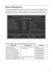
...//Mouse Restore On AC Power Loss [Yes] [S3 (STR)] [Disabled] Enabled]] [Enabled]] [Enabled]] [Enabled] [Enabled] [Last State] Item Help Yes/ No ACPI support for Disabled/Enabled Wake Up by PS/2 KB/Mouse Control wake up event for Operating System. KLIJ: Move Enter: Select F1: General Help +/-/: Value F10: Save F9: Optimized Defaults ESC: Exit The following screen shows the Power Management parameters and their default settings: CMOS Setup Utility- Power Management The Power Management menu lets you configure your own style of computer use...
...//Mouse Restore On AC Power Loss [Yes] [S3 (STR)] [Disabled] Enabled]] [Enabled]] [Enabled]] [Enabled] [Enabled] [Last State] Item Help Yes/ No ACPI support for Disabled/Enabled Wake Up by PS/2 KB/Mouse Control wake up event for Operating System. KLIJ: Move Enter: Select F1: General Help +/-/: Value F10: Save F9: Optimized Defaults ESC: Exit The following screen shows the Power Management parameters and their default settings: CMOS Setup Utility- Power Management The Power Management menu lets you configure your own style of computer use...
Service Guide
Page 36
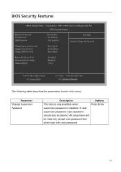
...be cleared. BIOS Security Features CMOS Setup Utility - BIOS Security Features Supervisor Password User Password HDD Password Change Supervisor Password Change User Password Change HDD Password : Not installed : Not Installed : Not Installed [Press Enter] [Press Enter] [Press Enter] Item Help Install or Change the Password Removable Device Boot Chassis Opened Warning Chassis Opened [Enabled] [Enabled] [Yes] KLIJ: Move Enter: Select F1: General Help +/-/: Value F10: Save ESC: Exit F9: Optimized Defaults The following table describes the parameters found in this menu: Parameter Change...
...be cleared. BIOS Security Features CMOS Setup Utility - BIOS Security Features Supervisor Password User Password HDD Password Change Supervisor Password Change User Password Change HDD Password : Not installed : Not Installed : Not Installed [Press Enter] [Press Enter] [Press Enter] Item Help Install or Change the Password Removable Device Boot Chassis Opened Warning Chassis Opened [Enabled] [Enabled] [Yes] KLIJ: Move Enter: Select F1: General Help +/-/: Value F10: Save ESC: Exit F9: Optimized Defaults The following table describes the parameters found in this menu: Parameter Change...
Service Guide
Page 78
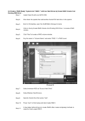
... SATA HDD. Step 3: Boot to finish create RAID1. Step 4: Click on the by 'Create RAID Volume from Existing HDD Drive ' to finish setup and start create RAID1. Step 8: Select Menber Hard Drive(s). Step 2: Shut down the system,then add another Serial ATA hard drive in RAID Level. Step 5: Step 6: Click "Next" at create a RAID volume window. Step 9: Specify Volume Size then press "next". Step 1: Install Vista OS with two Hard Drives...
... SATA HDD. Step 3: Boot to finish create RAID1. Step 4: Click on the by 'Create RAID Volume from Existing HDD Drive ' to finish setup and start create RAID1. Step 8: Select Menber Hard Drive(s). Step 2: Shut down the system,then add another Serial ATA hard drive in RAID Level. Step 5: Step 6: Click "Next" at create a RAID volume window. Step 9: Specify Volume Size then press "next". Step 1: Install Vista OS with two Hard Drives...
Service Guide
Page 85
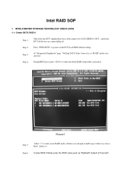
... STORAGE TECHNOLOGY CHECK (DOS) 1-1: Create SATA RAID 0 Step 1: Shut down the EUT, unplug the power cable,connect two SATA HDDS to EUT , check the EUT all devices are connect/plug ok Step 2: Press "PWR-BTTN" to enter into Intel RAID setup utility,as "MyRaid0",default is"Volume0". Step 4: During BIOS post, press to power on the EUT,Load BIOS default setting . Intel RAID SOP 1. Step 6: Create RAID 0 Mode,enter the RAID name,such as picture1.
... STORAGE TECHNOLOGY CHECK (DOS) 1-1: Create SATA RAID 0 Step 1: Shut down the EUT, unplug the power cable,connect two SATA HDDS to EUT , check the EUT all devices are connect/plug ok Step 2: Press "PWR-BTTN" to enter into Intel RAID setup utility,as "MyRaid0",default is"Volume0". Step 4: During BIOS post, press to power on the EUT,Load BIOS default setting . Intel RAID SOP 1. Step 6: Create RAID 0 Mode,enter the RAID name,such as picture1.
Service Guide
Page 88
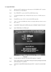
Step 5: Select "1" to enter create RAID mode ,if there is "Volume0". Step 9: Press "Create Volume" to create RAID1,it will pop the warning message that all devices are connect/plug ok Step 2: Press "PWR-BTTN" to power on the EUT,Load BIOS default setting . 1-2: Create SATA RAID 1 Step 1: Shut down the EUT, unplug the power cable,connect two SATA HDDS to EUT , check the EUT all data will...
Step 5: Select "1" to enter create RAID mode ,if there is "Volume0". Step 9: Press "Create Volume" to create RAID1,it will pop the warning message that all devices are connect/plug ok Step 2: Press "PWR-BTTN" to power on the EUT,Load BIOS default setting . 1-2: Create SATA RAID 1 Step 1: Shut down the EUT, unplug the power cable,connect two SATA HDDS to EUT , check the EUT all data will...
Service Guide
Page 89
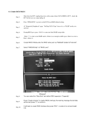
... confirm it ). Step 5: Select "1" to exit and install OS. Step 6: Create RAID 5 Mode,enter the RAID name,such as "RAID" mode,save and exit. Step 9: Press "Create Volume" to create RAID5,it will pop the warning message that all devices are connect/plug ok Step 2: Press "PWR-BTTN" to enter into Intel RAID setup utility. Step 4: During BIOS post, press to power on the EUT,Load BIOS default setting .
... confirm it ). Step 5: Select "1" to exit and install OS. Step 6: Create RAID 5 Mode,enter the RAID name,such as "RAID" mode,save and exit. Step 9: Press "Create Volume" to create RAID5,it will pop the warning message that all devices are connect/plug ok Step 2: Press "PWR-BTTN" to enter into Intel RAID setup utility. Step 4: During BIOS post, press to power on the EUT,Load BIOS default setting .
Service Guide
Page 90
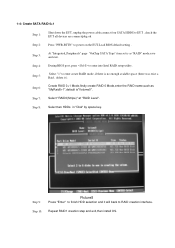
... RAID 0 Mode,enter the RAID name,such as "MyRaid0+1",default is as "RAID" mode,save and exit. Step 9: Picture8 Press "Enter" to finish HDD selection and it ). Step 10: Repeat RAID1 creation step and exit,then install OS. Step 3: At "Integrated_Peripherals" page "OnChip SATA Type" item set is "Volume0". Step 7: Select "RAID0(Stripe)" at "RAID Level". 1-4: Create SATA RAID 0+1 Step 1: Shut down the EUT, unplug the power cable,connect...
... RAID 0 Mode,enter the RAID name,such as "MyRaid0+1",default is as "RAID" mode,save and exit. Step 9: Picture8 Press "Enter" to finish HDD selection and it ). Step 10: Repeat RAID1 creation step and exit,then install OS. Step 3: At "Integrated_Peripherals" page "OnChip SATA Type" item set is "Volume0". Step 7: Select "RAID0(Stripe)" at "RAID Level". 1-4: Create SATA RAID 0+1 Step 1: Shut down the EUT, unplug the power cable,connect...


