
Acer Veriton X4620G Desktop Service Guide
Page 7
...Removing the Heat Sink Fan Assembly 32 Removing the Processor 34 Removing the Optical Drive 36 Removing the Hard Disk Drive 38 Removing the HDD-ODD Bracket 40 Removing the COM Port Cable and Printer Port Cable 42 Removing the Wireless LAN Card 44 Removing the VGA Card 46 Removing the Memory Modules 47 Removing the Power Supply 48 Removing the System Fan 50 Removing the Mainboard 52 Removing the Internal Speaker 56 Removing the Power Switch,OBR and LED Cable Assembly 57 Removing the USB/Front I/O Assembly and Card Reader Board 59 Removing the Intrusion Alarm Cable...
...Removing the Heat Sink Fan Assembly 32 Removing the Processor 34 Removing the Optical Drive 36 Removing the Hard Disk Drive 38 Removing the HDD-ODD Bracket 40 Removing the COM Port Cable and Printer Port Cable 42 Removing the Wireless LAN Card 44 Removing the VGA Card 46 Removing the Memory Modules 47 Removing the Power Supply 48 Removing the System Fan 50 Removing the Mainboard 52 Removing the Internal Speaker 56 Removing the Power Switch,OBR and LED Cable Assembly 57 Removing the USB/Front I/O Assembly and Card Reader Board 59 Removing the Intrusion Alarm Cable...

Acer Veriton X4620G Desktop Service Guide
Page 8
... the Optical Drive 88 Reinstalling the Processor 90 Reinstalling the Heat Sink Fan Assembly 93 Reinstalling the Front Bezel 95 Reinstalling the Side Panel 96 System Troubleshooting 97 Hardware Diagnostic Procedure 97 System Check Procedures 98 Power System Check 98 System External Inspection 98 System Internal Inspection 98 Beep Codes 99 Checkpoints 100 BIOS Recovery 103 Jumper and Connector Information 104 M/B Placement 104 Jumper Setting 106 Setting Jumper 107 Checking Connector 108 Connecting Case...
... the Optical Drive 88 Reinstalling the Processor 90 Reinstalling the Heat Sink Fan Assembly 93 Reinstalling the Front Bezel 95 Reinstalling the Side Panel 96 System Troubleshooting 97 Hardware Diagnostic Procedure 97 System Check Procedures 98 Power System Check 98 System External Inspection 98 System Internal Inspection 98 Beep Codes 99 Checkpoints 100 BIOS Recovery 103 Jumper and Connector Information 104 M/B Placement 104 Jumper Setting 106 Setting Jumper 107 Checking Connector 108 Connecting Case...

Acer Veriton X4620G Desktop Service Guide
Page 10
... DDRIII memory module. Optical disk drive • Support SATA 5.25" standard ODD. • Support DVD-ROM, DVD-SuperMulti (Label Flash), BD-DVD, BD-Combo. Graphics • Intel® HD Graphics Support • Dual independent display. • Digital display (HDMI/DVI/DP/eDP) and VGA. • DVMT 5.0 technology support. • Enhanced 3D and Clear Video technology support. • 1 DVI-I port at rear side. • 2 DP port on rear. • 3 Independent Digit Display support. • Need to measure VGA follow Acer VGA SOP. • Monitor compatible is listed...
... DDRIII memory module. Optical disk drive • Support SATA 5.25" standard ODD. • Support DVD-ROM, DVD-SuperMulti (Label Flash), BD-DVD, BD-Combo. Graphics • Intel® HD Graphics Support • Dual independent display. • Digital display (HDMI/DVI/DP/eDP) and VGA. • DVMT 5.0 technology support. • Enhanced 3D and Clear Video technology support. • 1 DVI-I port at rear side. • 2 DP port on rear. • 3 Independent Digit Display support. • Need to measure VGA follow Acer VGA SOP. • Monitor compatible is listed...

Acer Veriton X4620G Desktop Service Guide
Page 11
... Gbt LAN controller/PHY for China (option, default not). Support Wake up on board buzzer Chapter 1 3 RJ-45 Back panel port with Link/Activity LEDs. Can support 4KV surge for VX6 series. Audio • Chip : HD audio codec ALC662-VD HD codec 5.1 • Connectors support: • Rear 3 jack follow HD audio definition (ALC662-VD). • Audio jacks color coding: should meet Microsoft Windows Logo Program Device Requirements: Audio-0002. • 1 front panel audio header (2*5). • 1 internal speaker...
... Gbt LAN controller/PHY for China (option, default not). Support Wake up on board buzzer Chapter 1 3 RJ-45 Back panel port with Link/Activity LEDs. Can support 4KV surge for VX6 series. Audio • Chip : HD audio codec ALC662-VD HD codec 5.1 • Connectors support: • Rear 3 jack follow HD audio definition (ALC662-VD). • Audio jacks color coding: should meet Microsoft Windows Logo Program Device Requirements: Audio-0002. • 1 front panel audio header (2*5). • 1 internal speaker...

Acer Veriton X4620G Desktop Service Guide
Page 12
...; 1 x PCI Express x 1 slot. • 4 x SATA connectors(6Gb/s*2 and 3Gb/s*2 for clear CMOS • 1 x BIOS write protect header • 1 x on board buzzer • 1 x 2pin OBR header • 2 x reserved 2pin GPIO connector • 1 x Serial port header (COM2) (near rear IO) • 1 x TPM DB header (2x10)(*check Acer's TPM DB spec) • 1 x 2pin Intrusion Alarm connector • 1 x LPT 2*13pin header (near rear IO) • 1 x 2*4 pin internal speaker header • 1 x 3pin ME enable/disable connector (with 1 jumper...
...; 1 x PCI Express x 1 slot. • 4 x SATA connectors(6Gb/s*2 and 3Gb/s*2 for clear CMOS • 1 x BIOS write protect header • 1 x on board buzzer • 1 x 2pin OBR header • 2 x reserved 2pin GPIO connector • 1 x Serial port header (COM2) (near rear IO) • 1 x TPM DB header (2x10)(*check Acer's TPM DB spec) • 1 x 2pin Intrusion Alarm connector • 1 x LPT 2*13pin header (near rear IO) • 1 x 2*4 pin internal speaker header • 1 x 3pin ME enable/disable connector (with 1 jumper...

Acer Veriton X4620G Desktop Service Guide
Page 16
Rear Panel No. Component 9 Expansion slot(graphics card ect.) 10 line-in jack 11 Serial port 12 Parallel port 13 RJ45 LAN port 14 Serial port 15 PS2 mouse connector 16 Power connector Chapter 1 Component 1 Fan aperture 2 PS2 keyboard connector 3 DVI-D port 4 DP port 5 USB 3.0 ports 6 USB 2.0 ports 7 Line-out jack 8 Microphone jack 8 No.
Rear Panel No. Component 9 Expansion slot(graphics card ect.) 10 line-in jack 11 Serial port 12 Parallel port 13 RJ45 LAN port 14 Serial port 15 PS2 mouse connector 16 Power connector Chapter 1 Component 1 Fan aperture 2 PS2 keyboard connector 3 DVI-D port 4 DP port 5 USB 3.0 ports 6 USB 2.0 ports 7 Line-out jack 8 Microphone jack 8 No.

Acer Veriton X4620G Desktop Service Guide
Page 17
... ALC662-VD LAN controller Intel 82579LM USB controller Intel Q77 HDD controller Intel Q77 Chapter 1 9 Hardware Specifications and Configurations Processor Item Specification Processor Type Intel Ivy Bridge/ Sandy Bridge Processor Socket Type Intel Socket LGA 1155 pin FSB 1333 MHz Minimum operating speed 0 MHz (If Stop CPU Clock in Sleep State in BIOS Setup is set to Enabled.) BIOS Item Specification BIOS code programer AMI Kernel with Acer skin BIOS version P01-A0 BIOS ROM type SPI Flash BIOS ROM size 8MBytes Support protocol SMBIOS(DMI)2.7 Device Boot Support 1st...
... ALC662-VD LAN controller Intel 82579LM USB controller Intel Q77 HDD controller Intel Q77 Chapter 1 9 Hardware Specifications and Configurations Processor Item Specification Processor Type Intel Ivy Bridge/ Sandy Bridge Processor Socket Type Intel Socket LGA 1155 pin FSB 1333 MHz Minimum operating speed 0 MHz (If Stop CPU Clock in Sleep State in BIOS Setup is set to Enabled.) BIOS Item Specification BIOS code programer AMI Kernel with Acer skin BIOS version P01-A0 BIOS ROM type SPI Flash BIOS ROM size 8MBytes Support protocol SMBIOS(DMI)2.7 Device Boot Support 1st...

Acer Veriton X4620G Desktop Service Guide
Page 18
.../2GB/4GB 1G ~4GB Maximum System Memory Supported 1G~16GB System Memory Item Specification Memory slot number 4 slot Support Memory size per socket 1GB/2GB/4GB Support memory type DDRIII Support memory interface DDR III 1333/1066 MHz Support memory voltage 1.5V Support memory module package 240-pin DDRIII Support to parity check feature Yes Support to error correction code (ECC) feature No Memory module combinations You can install memory modules in any combination as long as...
.../2GB/4GB 1G ~4GB Maximum System Memory Supported 1G~16GB System Memory Item Specification Memory slot number 4 slot Support Memory size per socket 1GB/2GB/4GB Support memory type DDRIII Support memory interface DDR III 1333/1066 MHz Support memory voltage 1.5V Support memory module package 240-pin DDRIII Support to parity check feature Yes Support to error correction code (ECC) feature No Memory module combinations You can install memory modules in any combination as long as...

Acer Veriton X4620G Desktop Service Guide
Page 19
Power Management Devices S1 S3 S4 Power Button V V V USB Keyboard/Mouse V V N/A PME Disabled Disabled Disabled RCT Disabled Disabled Disabled WOR Disabled Disabled Disabled • Devices wake up from S3 should be less than. • Devices wake up from S5 should be less than 10 seconds. S5 V N/A Disabled Disabled Disabled Chapter 1 11 SATA Interface Item SATA controller Number of SATA channel Support mode Specification Intel Q77 SATA X4(6Gb/s*2SATAIII and 3Gb/s*2SATAII) RAID/AHCI/IDE mode option USB Port Item Universal HCI USB Class USB Connectors Quantity ...
Power Management Devices S1 S3 S4 Power Button V V V USB Keyboard/Mouse V V N/A PME Disabled Disabled Disabled RCT Disabled Disabled Disabled WOR Disabled Disabled Disabled • Devices wake up from S3 should be less than. • Devices wake up from S5 should be less than 10 seconds. S5 V N/A Disabled Disabled Disabled Chapter 1 11 SATA Interface Item SATA controller Number of SATA channel Support mode Specification Intel Q77 SATA X4(6Gb/s*2SATAIII and 3Gb/s*2SATAII) RAID/AHCI/IDE mode option USB Port Item Universal HCI USB Class USB Connectors Quantity ...

Acer Veriton X4620G Desktop Service Guide
Page 21
... the power management configuration • When changing the password or making other changes to the security setup • When a configuration error is detected by the system and you are already properly configured and optimized, there is no need to run the CMOS Setup Utility, make changes to make sure that you repeatedly receive Run Setup messages, the battery may not be retained when power is turned off. This memory area is not part of the system RAM...
... the power management configuration • When changing the password or making other changes to the security setup • When a configuration error is detected by the system and you are already properly configured and optimized, there is no need to run the CMOS Setup Utility, make changes to make sure that you repeatedly receive Run Setup messages, the battery may not be retained when power is turned off. This memory area is not part of the system RAM...

Acer Veriton X4620G Desktop Service Guide
Page 23
... Build Date Processor Core Frequency Count Memory Size Product Name System Serial Number Asset Tag Number System Date System Time (hh:mm:ss) Description Version number of the system. Product name of the BIOS setup utility. Serial number of this system. Date when the BIOS setup utility was built Type of system memory installed on the system. Set the date following main setup categories. Main The Setup Main menu includes the...
... Build Date Processor Core Frequency Count Memory Size Product Name System Serial Number Asset Tag Number System Date System Time (hh:mm:ss) Description Version number of the system. Product name of the BIOS setup utility. Serial number of this system. Date when the BIOS setup utility was built Type of system memory installed on the system. Set the date following main setup categories. Main The Setup Main menu includes the...

Acer Veriton X4620G Desktop Service Guide
Page 27
Enables or disables support for onboard network controller. Use this item to enable or disable the onboard COM2 serial port, and to assign a portaddress. Option Enabled Disabled Native IDE RAID AHCI Enabled Disabled Enabled Disabled Auto Floppy Hard Disk Enabled Disabled Enabled Disabled Enabled Disabled Enabled Disabled Disabled 3F8/IRQ4 3E8/IRQ4 Disabled 2F8/IRQ3 2E8/IRQ3 Disabled 378 278 3BC Chapter 2 19 If Auto, USB device equal or less than 2GB will be used to force a HDD formatted drive to assign a portaddress. Forced FDD option can be...
Enables or disables support for onboard network controller. Use this item to enable or disable the onboard COM2 serial port, and to assign a portaddress. Option Enabled Disabled Native IDE RAID AHCI Enabled Disabled Enabled Disabled Auto Floppy Hard Disk Enabled Disabled Enabled Disabled Enabled Disabled Enabled Disabled Disabled 3F8/IRQ4 3E8/IRQ4 Disabled 2F8/IRQ3 2E8/IRQ3 Disabled 378 278 3BC Chapter 2 19 If Auto, USB device equal or less than 2GB will be used to force a HDD formatted drive to assign a portaddress. Forced FDD option can be...

Acer Veriton X4620G Desktop Service Guide
Page 32
... the case. Enabled Disabled This item displays the TPM status to access the sub menu. This item enables or disables support the boot from USB mass storage Enabled devices. Enabled Disabled Clear This item indicates whether the case has been opened up, and the item belowindicates the current status of the TPM operation. Security Parameter Supervisor Password User Password HDD Password Change Supervisor Password Change HDD Password TPM Support TPM State TPM Operation TPM Enabled Status TPM Active Status TPM Owner Status Removable Device Boot BIOS Write...
... the case. Enabled Disabled This item displays the TPM status to access the sub menu. This item enables or disables support the boot from USB mass storage Enabled devices. Enabled Disabled Clear This item indicates whether the case has been opened up, and the item belowindicates the current status of the TPM operation. Security Parameter Supervisor Password User Password HDD Password Change Supervisor Password Change HDD Password TPM Support TPM State TPM Operation TPM Enabled Status TPM Active Status TPM Owner Status Removable Device Boot BIOS Write...

Acer Veriton X4620G Desktop Service Guide
Page 34
...available optical drives. Enabled Disabled Determines whether the system will stop for an error during startup. EFI Hard Disk CD^DVD Removable Device LAN Press Enter to access the EFI Device Priority submenu and specify the boot device priority sequence from the available devices. Boot Options 1st/2nd/3rd/4th/5th Boot Device EFI Device Priority Hard Disk Drive Priority Optical Disk Drive Priority Removable Device Priority Network Device Priority Quiet Boot Halt On Specifies the boot order from available EFI devices. When enabled, the BIOS splash screen displays during startup.
...available optical drives. Enabled Disabled Determines whether the system will stop for an error during startup. EFI Hard Disk CD^DVD Removable Device LAN Press Enter to access the EFI Device Priority submenu and specify the boot device priority sequence from the available devices. Boot Options 1st/2nd/3rd/4th/5th Boot Device EFI Device Priority Hard Disk Drive Priority Optical Disk Drive Priority Removable Device Priority Network Device Priority Quiet Boot Halt On Specifies the boot order from available EFI devices. When enabled, the BIOS splash screen displays during startup.
Acer Veriton X4620G Desktop Service Guide
Page 105
Chapter 4 System Troubleshooting This chapter provides instructions on page 99 to determine which corrective action to test Acer products. NonAcerproducts, prototype cards, or modified options can give false errors and invalid systemresponses. 1. Refer to "Power System check" on page 98 and "Beep Codes" on how to troubleshoot system hardware problems. Hardware Diagnostic Procedure IMPORTANT:The diagnostic tests described in as much detail as possible. 2. Obtain the failing symptoms...
Chapter 4 System Troubleshooting This chapter provides instructions on page 99 to determine which corrective action to test Acer products. NonAcerproducts, prototype cards, or modified options can give false errors and invalid systemresponses. 1. Refer to "Power System check" on page 98 and "Beep Codes" on how to troubleshoot system hardware problems. Hardware Diagnostic Procedure IMPORTANT:The diagnostic tests described in as much detail as possible. 2. Obtain the failing symptoms...

Acer Veriton X4620G Desktop Service Guide
Page 108
... displays checkpoints thatoccur after the video card has been activated. Copies BIOS from ROM to lower system memory and control is given to memory in scratch CMOS. Restore CPUID value back into memory. Early Boot Strap Processor (BSP) initialization like microcode update, frequency and other components before memory detection. Early chipset initialization is enabled at this point. Serial port is done. Save power-on a LED display. Re-enable CACHE. Main BIOS checksum is disabled...
... displays checkpoints thatoccur after the video card has been activated. Copies BIOS from ROM to lower system memory and control is given to memory in scratch CMOS. Restore CPUID value back into memory. Early Boot Strap Processor (BSP) initialization like microcode update, frequency and other components before memory detection. Early chipset initialization is enabled at this point. Serial port is done. Save power-on a LED display. Re-enable CACHE. Main BIOS checksum is disabled...

Acer Veriton X4620G Desktop Service Guide
Page 110
... validity of the flash part. Make flash write enabled through chipset and OEM specific method. The recovery file size does not equal the found . Bootblock Recovery Code Checkpoints The Bootblock recovery code gets control when the BIOS determines that a BIOS recovery needs to read from add-in PCI devices. Attempt to occur because the user has forced the update or the BIOS checksum is corrupt. Read error occurred on system configuration. Start reading FAT table...
... validity of the flash part. Make flash write enabled through chipset and OEM specific method. The recovery file size does not equal the found . Bootblock Recovery Code Checkpoints The Bootblock recovery code gets control when the BIOS determines that a BIOS recovery needs to read from add-in PCI devices. Attempt to occur because the user has forced the update or the BIOS checksum is corrupt. Read error occurred on system configuration. Start reading FAT table...

Acer Veriton X4620G Desktop Service Guide
Page 111
... and then press Ctrl + Home. 4. Press power button to flash BIOS ROM. 1. The BIOS recovery function will auto reboot. 6. Please enter the setup menu to a bootable USB flash drive(Disk on Key, DOK). 2. Chapter 4 103 Put the AMIBoot.ROM to load default after system reboot. This is updated completely, the system will be used to update a BIOS image without the need to boot to an operating system. Install the DOK to the system. 3. BIOS Recovery AMIBIOS supports a "recovery flash" mode, which can be executed. 5.
... and then press Ctrl + Home. 4. Press power button to flash BIOS ROM. 1. The BIOS recovery function will auto reboot. 6. Please enter the setup menu to a bootable USB flash drive(Disk on Key, DOK). 2. Chapter 4 103 Put the AMIBoot.ROM to load default after system reboot. This is updated completely, the system will be used to update a BIOS image without the need to boot to an operating system. Install the DOK to the system. 3. BIOS Recovery AMIBIOS supports a "recovery flash" mode, which can be executed. 5.

Acer Veriton X4620G Desktop Service Guide
Page 113
...Bridge Processor CPU cooling fan connector 240-Pin DDR3 SDRAM slots (Channel A: DIMM2, DIMM4 Channel B: DIMM1, DIMM3) System cooling fan connector Standard 24-pin ATX power connector Serial ATA 6.0Gb/s connectors Front panel USB 3.0 connector Buzzer Opened Chassis detective header Front panel switch/LED header One Button Recovery header Front panel USB 2.0 headers Serial ATA 3.0Gb/s connectors Front panel USB 2.0 header (for card reader) Clear CMOS header with jumper BIOS flash protect header with jumper ME Disable header with jumper Speaker header Front panel audio header SPDIF out header PCI...
...Bridge Processor CPU cooling fan connector 240-Pin DDR3 SDRAM slots (Channel A: DIMM2, DIMM4 Channel B: DIMM1, DIMM3) System cooling fan connector Standard 24-pin ATX power connector Serial ATA 6.0Gb/s connectors Front panel USB 3.0 connector Buzzer Opened Chassis detective header Front panel switch/LED header One Button Recovery header Front panel USB 2.0 headers Serial ATA 3.0Gb/s connectors Front panel USB 2.0 header (for card reader) Clear CMOS header with jumper BIOS flash protect header with jumper ME Disable header with jumper Speaker header Front panel audio header SPDIF out header PCI...
Acer Veriton X4620G Desktop Service Guide
Page 114
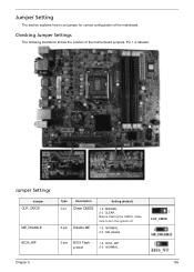
Jumper Settings Jumper CLR_CMOS ME_DISABLE BIOS_WP Type 3-pin 3-pin Description Clear CMOS Disable ME Setting (default) 1-2: NORMAL 2-3: CLEAR Before clearing the CMOS, make sure to set jumper for correct configuration of the motherboard jumpers. Pin 1 is labeled. Jumper Setting The section explains how to turn the system off. 1-2: NORMAL 2-3: ME disable 3-pin BIOS Flash protect 1-2: BIOS_WP 2-3: NORMAL CLR_CMOS Chapter 5 106 Checking Jumper Settings The following illustration shows the location of the mainboard.
Jumper Settings Jumper CLR_CMOS ME_DISABLE BIOS_WP Type 3-pin 3-pin Description Clear CMOS Disable ME Setting (default) 1-2: NORMAL 2-3: CLEAR Before clearing the CMOS, make sure to set jumper for correct configuration of the motherboard jumpers. Pin 1 is labeled. Jumper Setting The section explains how to turn the system off. 1-2: NORMAL 2-3: ME disable 3-pin BIOS Flash protect 1-2: BIOS_WP 2-3: NORMAL CLR_CMOS Chapter 5 106 Checking Jumper Settings The following illustration shows the location of the mainboard.


