
X241W Service Guide
Page 9
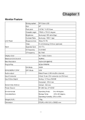
Chapter 1 Monitor Feature LCD Panel Input Display Color Maximum Dot Clock ® Max Resolution Plug & Play EPA ENERGY STAY Audio output Input Connector Input Video Signal Screen Size (Active) Power Source Environmental Considerations Weight (N.W.) Dimension Driving system Size Pixel pitch Viewable angle Brightness Contrast Ratio Response time Video Separate Sync H-Frequency V-...
Chapter 1 Monitor Feature LCD Panel Input Display Color Maximum Dot Clock ® Max Resolution Plug & Play EPA ENERGY STAY Audio output Input Connector Input Video Signal Screen Size (Active) Power Source Environmental Considerations Weight (N.W.) Dimension Driving system Size Pixel pitch Viewable angle Brightness Contrast Ratio Response time Video Separate Sync H-Frequency V-...
X241W Service Guide
Page 33
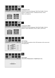
OSD Settings: This changes the position of the OSD window on the screen and the staying time. Select from English, German, Spanish, Simplified Chinese, Traditional Chinese, French, Italian, and Japanese. Input signal: Select either Analog Input or Digital Input video. Language for Asia: Select the OSD menu language. Select from English, German, Spanish, Russia, Nederlands, French, Italian, and Finnish. Language for EMEA: Select the OSD menu language.
OSD Settings: This changes the position of the OSD window on the screen and the staying time. Select from English, German, Spanish, Simplified Chinese, Traditional Chinese, French, Italian, and Japanese. Input signal: Select either Analog Input or Digital Input video. Language for Asia: Select the OSD menu language. Select from English, German, Spanish, Russia, Nederlands, French, Italian, and Finnish. Language for EMEA: Select the OSD menu language.

X241W Service Guide
Page 36
.... IN ORDER FOR THIS MONITOR TO OPERATE PROPERLY, THERE MUST BE A VIDEO INPUT SIGNAL. After the video input signal is restored, full power is restored and the display is no video-input signal present. The display is completely off. The voltage rating for connection to conserve electrical ... Protection Agency (EPA) and The Swedish Confederation Employees (NUTEK). The other end terminates with NEMA 5-15 style and is no video input signal this monitor, following a time-out period, will automatically switch to an OFF mode. This monitor meets the Green monitor standards as set ...
.... IN ORDER FOR THIS MONITOR TO OPERATE PROPERLY, THERE MUST BE A VIDEO INPUT SIGNAL. After the video input signal is restored, full power is restored and the display is no video-input signal present. The display is completely off. The voltage rating for connection to conserve electrical ... Protection Agency (EPA) and The Swedish Confederation Employees (NUTEK). The other end terminates with NEMA 5-15 style and is no video input signal this monitor, following a time-out period, will automatically switch to an OFF mode. This monitor meets the Green monitor standards as set ...
X241W Service Guide
Page 52
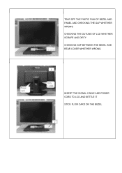
TEAR OFF THE PASTIC FILM OF BEZEL AND PANEL AND CHECKING THE GAP WHETHER WRONG CHECKING THE OUTLINE OF LCD WHETHER SCRAPE AND DIRTY CHECKING GAP BETWEEN THE BEZEL AND REAR COVER WHETHER WRONG INSERT THE SIGNAL CABLE AND POWER CORD TO LCD AND SETTLE IT STICK FLOW CARD ON THE BEZEL
TEAR OFF THE PASTIC FILM OF BEZEL AND PANEL AND CHECKING THE GAP WHETHER WRONG CHECKING THE OUTLINE OF LCD WHETHER SCRAPE AND DIRTY CHECKING GAP BETWEEN THE BEZEL AND REAR COVER WHETHER WRONG INSERT THE SIGNAL CABLE AND POWER CORD TO LCD AND SETTLE IT STICK FLOW CARD ON THE BEZEL
X241W Service Guide
Page 57
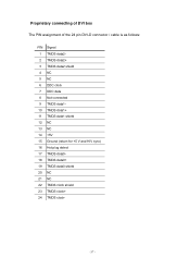
Proprietary connecting of DVI box The PIN assignment of the 24 pin DVI-D connector / cable is as follows: PIN Signal 1 TMDS data22 TMDS data2+ 3 TMDS data2 shield 4 NC 5 NC 6 DDC clock 7 DDC data 8 Not connected 9 TMDS data110 TMDS data1+ 11 TMDS data1 shield 12 NC 13 NC 14 +5V 15 Ground (return for +5 V and H/V sync) 16 Hot plug detect 17 TMDS data018 TMDS data0+ 19 TMDS data0 shield 20 NC 21 NC 22 TMDS clock shield 23 TMDS clock+ 24 TMDS clock- - 57 -
Proprietary connecting of DVI box The PIN assignment of the 24 pin DVI-D connector / cable is as follows: PIN Signal 1 TMDS data22 TMDS data2+ 3 TMDS data2 shield 4 NC 5 NC 6 DDC clock 7 DDC data 8 Not connected 9 TMDS data110 TMDS data1+ 11 TMDS data1 shield 12 NC 13 NC 14 +5V 15 Ground (return for +5 V and H/V sync) 16 Hot plug detect 17 TMDS data018 TMDS data0+ 19 TMDS data0 shield 20 NC 21 NC 22 TMDS clock shield 23 TMDS clock+ 24 TMDS clock- - 57 -


