
X241W Service Guide
Page 2
... or implied, with respect to change without the prior written permission of Intel Corporation. Other brand and product names are trademarks of Acer Incorporated. All rights reserved. No part of this manual is sold or licensed "as is subject to the contents hereof and specifically disclaims any warranties of all necessary servicing, repair, and any incidental or...
... or implied, with respect to change without the prior written permission of Intel Corporation. Other brand and product names are trademarks of Acer Incorporated. All rights reserved. No part of this manual is sold or licensed "as is subject to the contents hereof and specifically disclaims any warranties of all necessary servicing, repair, and any incidental or...
X241W Service Guide
Page 4
... Before using this information and the product it will NOT be noted in the printed Service Guide, for ACER-AUTHORIZED SERVICE PROVIDERS, your regional Acer office to order FRU parts for repair and Service of a machine (e.g. If, for whatever reason, a part number change is made, it supports, please...Acer's "global" product offering. this Service Guide provides you should check the most up-to those given in the FRU list of this printed Service Guide. In such cases, please contact your regional office MAY have a DIFFERENT part number code to -date information available on card...
... Before using this information and the product it will NOT be noted in the printed Service Guide, for ACER-AUTHORIZED SERVICE PROVIDERS, your regional Acer office to order FRU parts for repair and Service of a machine (e.g. If, for whatever reason, a part number change is made, it supports, please...Acer's "global" product offering. this Service Guide provides you should check the most up-to those given in the FRU list of this printed Service Guide. In such cases, please contact your regional office MAY have a DIFFERENT part number code to -date information available on card...
X241W Service Guide
Page 5
... radio frequency energy, and if not installed and used in accordance with the instructions, may cause harmful interference to radio communications. WARNING: (FOR FCC CERTIFIED MODELS) NOTE: this equipment has been tested and found to comply with the limits for help. Consult the dealer or an experienced radio/TV technician for a Class B digital device, pursuant to Part 15...
... radio frequency energy, and if not installed and used in accordance with the instructions, may cause harmful interference to radio communications. WARNING: (FOR FCC CERTIFIED MODELS) NOTE: this equipment has been tested and found to comply with the limits for help. Consult the dealer or an experienced radio/TV technician for a Class B digital device, pursuant to Part 15...
X241W Service Guide
Page 6
... a wall or shelf, use a mounting kit approved by the manufacture or sold with a third (grounding) pin. Use only a trolley or stand recommended by the manufacture and follow the kit instructions. z Slots and openings in fire or electric shock. This plug will protect the monitor from the type of the cabinet area provided for long periods of power supplied to power surges. opening or removing covers...
... a wall or shelf, use a mounting kit approved by the manufacture or sold with a third (grounding) pin. Use only a trolley or stand recommended by the manufacture and follow the kit instructions. z Slots and openings in fire or electric shock. This plug will protect the monitor from the type of the cabinet area provided for long periods of power supplied to power surges. opening or removing covers...
X241W Service Guide
Page 7
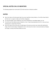
... as a missing pixel or a pixel lit all of 99.99% or more. In this case, the screen is displayed for hours. - 7 - NOTES z Due to the nature of the LCD screen, an afterimage of the fluorescent light, the screen may remain after switching the image, when the same image is recovered slowly by changing the image or turning off the Power Switch and then turn it on the...
... as a missing pixel or a pixel lit all of 99.99% or more. In this case, the screen is displayed for hours. - 7 - NOTES z Due to the nature of the LCD screen, an afterimage of the fluorescent light, the screen may remain after switching the image, when the same image is recovered slowly by changing the image or turning off the Power Switch and then turn it on the...
X241W Service Guide
Page 9
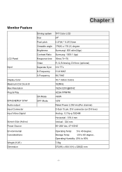
Chapter 1 Monitor Feature LCD Panel Input Display Color Maximum Dot Clock ® Max Resolution Plug & Play EPA ENERGY STAY Audio output Input Connector Input Video Signal Screen Size (Active) Power Source Environmental Considerations Weight (N.W.) Dimension Driving system Size Pixel pitch Viewable angle Brightness Contrast Ratio Response time Video Separate Sync H-Frequency V-Frequency ON Mode OFF Mode TFT Color LCD 24" 0.27(H) * 0.27(V)mm 178(H) x 178 (V) degree Sumsungl: 500 cd/m2(typ) Sumsung: 1000:1 (typ) 16ms (Tr+Tf) R, G, B Analog, DVI box (optional) H/V TTL 31-81KHZ...
Chapter 1 Monitor Feature LCD Panel Input Display Color Maximum Dot Clock ® Max Resolution Plug & Play EPA ENERGY STAY Audio output Input Connector Input Video Signal Screen Size (Active) Power Source Environmental Considerations Weight (N.W.) Dimension Driving system Size Pixel pitch Viewable angle Brightness Contrast Ratio Response time Video Separate Sync H-Frequency V-Frequency ON Mode OFF Mode TFT Color LCD 24" 0.27(H) * 0.27(V)mm 178(H) x 178 (V) degree Sumsungl: 500 cd/m2(typ) Sumsung: 1000:1 (typ) 16ms (Tr+Tf) R, G, B Analog, DVI box (optional) H/V TTL 31-81KHZ...
X241W Service Guide
Page 31
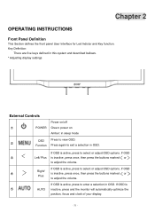
...;1 POWER Green: power on Amber: in OSD. If OSD ○3 Left/ Plus is active, press to view OSD. If OSD is inactive, press once, then press the buttons marked or to adjust the volume. Function Press again to adjust the volume. If OSD ○4 Right/ Plus is ○5 AUTO inactive, press and the monitor will automatically optimize the position, focus and clock of your display. - 31 - Chapter 2 OPERATING INSTRUCTIONS Front Panel...
...;1 POWER Green: power on Amber: in OSD. If OSD ○3 Left/ Plus is active, press to view OSD. If OSD is inactive, press once, then press the buttons marked or to adjust the volume. Function Press again to adjust the volume. If OSD ○4 Right/ Plus is ○5 AUTO inactive, press and the monitor will automatically optimize the position, focus and clock of your display. - 31 - Chapter 2 OPERATING INSTRUCTIONS Front Panel...
X241W Service Guide
Page 32
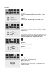
... horizontal distortion and makes the picture clear and sharp. V-Position: This adjusts the vertical. Clock: If there are three ways to adjust color: Warm (reddish white) Cool (bluish white) User (you desire) Brightness: This adjusts the brightness of the picture on the background of the screen, this renders them less noticeable by minimizing their size. OSD menu Contrast: This adjusts dark and light shades of color relative to the intensity you can adjust the colors red, green...
... horizontal distortion and makes the picture clear and sharp. V-Position: This adjusts the vertical. Clock: If there are three ways to adjust color: Warm (reddish white) Cool (bluish white) User (you desire) Brightness: This adjusts the brightness of the picture on the background of the screen, this renders them less noticeable by minimizing their size. OSD menu Contrast: This adjusts dark and light shades of color relative to the intensity you can adjust the colors red, green...
X241W Service Guide
Page 33
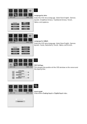
OSD Settings: This changes the position of the OSD window on the screen and the staying time. Input signal: Select either Analog Input or Digital Input video. Language for EMEA: Select the OSD menu language. Select from English, German, Spanish, Simplified Chinese, Traditional Chinese, French, Italian, and Japanese. Select from English, German, Spanish, Russia, Nederlands, French, Italian, and Finnish. Language for Asia: Select the OSD menu language.
OSD Settings: This changes the position of the OSD window on the screen and the staying time. Input signal: Select either Analog Input or Digital Input video. Language for EMEA: Select the OSD menu language. Select from English, German, Spanish, Simplified Chinese, Traditional Chinese, French, Italian, and Japanese. Select from English, German, Spanish, Russia, Nederlands, French, Italian, and Finnish. Language for Asia: Select the OSD menu language.

X241W Service Guide
Page 35
... its display capabilities. LED Definition The system equips one dual color (blue/amber) led to indict system status and defined as bellows: LED Color Green System Status System in normal operation mode Amber System in power-saving mode Dark System in power-off mode LOGO: When the monitor is power on, the LOGO will be showed in two levels, DDC2B. HOW TO OPTIMIZE THE DOS-MODE Plug and play Plug...
... its display capabilities. LED Definition The system equips one dual color (blue/amber) led to indict system status and defined as bellows: LED Color Green System Status System in normal operation mode Amber System in power-saving mode Dark System in power-off mode LOGO: When the monitor is power on, the LOGO will be showed in two levels, DDC2B. HOW TO OPTIMIZE THE DOS-MODE Plug and play Plug...

X241W Service Guide
Page 36
... cord. Please note that power supply card needs to a "Screen Saver" feature except the display is automatically redrawn. This reduces the monitor's internal power supply consumption. USING THE RIGHT POWER CORD The accessory power cord for the power cord shall be 125 volt AC. After the video input signal is restored, full power is restored and the display is completely off. The appearance is similar to use a cord set by pressing a key on type connector body, rated...
... cord. Please note that power supply card needs to a "Screen Saver" feature except the display is automatically redrawn. This reduces the monitor's internal power supply consumption. USING THE RIGHT POWER CORD The accessory power cord for the power cord shall be 125 volt AC. After the video input signal is restored, full power is restored and the display is completely off. The appearance is similar to use a cord set by pressing a key on type connector body, rated...

X241W Service Guide
Page 37
Chapter 3 Machine assembly This chapter contains step-by-step procedures on a soft surface when mounting or removing the base. 3. Wear gloves. Note : The monitor surface is susceptible to avoid mismatch when putting back the components. 2. Therefore, lay the monitor on how to assemble the monitor for the different components vary in size. Front View: ( unit : mm ) - 37 - The screws for maintenance and trouble shooting NOTE : 1. During the disassembly process, group the screws with the corresponding to scratching!
Chapter 3 Machine assembly This chapter contains step-by-step procedures on a soft surface when mounting or removing the base. 3. Wear gloves. Note : The monitor surface is susceptible to avoid mismatch when putting back the components. 2. Therefore, lay the monitor on how to assemble the monitor for the different components vary in size. Front View: ( unit : mm ) - 37 - The screws for maintenance and trouble shooting NOTE : 1. During the disassembly process, group the screws with the corresponding to scratching!
X241W Service Guide
Page 41
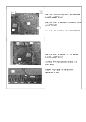
LOCK UP3*PCS SCREW(F3*6-T) WITH POWER BOARD AS LEFT SHOW LOCK UP 1*PCS SCREW(M4.0*8-B) WITH INV/B AS LEFT SHOW PUT THE POWER/MYLAR TO THE SHIELDING LOCK UP 3*PCS SCREW(F3*6T) WITH MAIN BOARD AS LEFT SHOW GET THE INVERTER BOARD / CABLE AND CHECKING INSERT THE CABLE TO THE SINK OF INVERTER BOARD
LOCK UP3*PCS SCREW(F3*6-T) WITH POWER BOARD AS LEFT SHOW LOCK UP 1*PCS SCREW(M4.0*8-B) WITH INV/B AS LEFT SHOW PUT THE POWER/MYLAR TO THE SHIELDING LOCK UP 3*PCS SCREW(F3*6T) WITH MAIN BOARD AS LEFT SHOW GET THE INVERTER BOARD / CABLE AND CHECKING INSERT THE CABLE TO THE SINK OF INVERTER BOARD
X241W Service Guide
Page 43
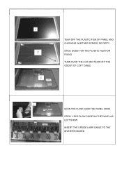
TEAR OFF THE PLASTIC FILM OF PANEL AND CHECKING WHETHER SCRAPE OR DIRTY STICK GOOEY ON THE PLASTIC FILM FOR FIXING TURN OVER THE LCD AND TEAR OFF THE GOOEY OF CCFT CABLE SCAN THE FLOW CARD THE PANEL CODE STICK 1*PCS FLOW CODE ON THE PANEL AS LEFT SHOW INSERT THE UPSIDE LAMP CABLE TO THE INVERTER BOARD
TEAR OFF THE PLASTIC FILM OF PANEL AND CHECKING WHETHER SCRAPE OR DIRTY STICK GOOEY ON THE PLASTIC FILM FOR FIXING TURN OVER THE LCD AND TEAR OFF THE GOOEY OF CCFT CABLE SCAN THE FLOW CARD THE PANEL CODE STICK 1*PCS FLOW CODE ON THE PANEL AS LEFT SHOW INSERT THE UPSIDE LAMP CABLE TO THE INVERTER BOARD
X241W Service Guide
Page 50
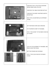
CHECKING THE AL FOIL(5*PCS) WHETHER WRONG MODE AND LOCATION CHECKING THE CABLE WHETHER SETTLED CHECKING THE GOOEY WHETHER UNSTICK OR SETTLED ROCK THE LCD WHETHER ANY DIFFERENT THINGS GET THE REAR COVER AND CHECKING PUT THE REAR COVER TO THE BEZEL STICK 1*PCS GOOEY TO THE REAR COVER AS LEFT SHOW LOCK UP 2*PCS SCREWS TO THE BEZEL AND REAR COVER FOR FIXING GET THE STANDS AND CHECKING STICK 1*PCS FLOW CODE ON THE REAR COVER
CHECKING THE AL FOIL(5*PCS) WHETHER WRONG MODE AND LOCATION CHECKING THE CABLE WHETHER SETTLED CHECKING THE GOOEY WHETHER UNSTICK OR SETTLED ROCK THE LCD WHETHER ANY DIFFERENT THINGS GET THE REAR COVER AND CHECKING PUT THE REAR COVER TO THE BEZEL STICK 1*PCS GOOEY TO THE REAR COVER AS LEFT SHOW LOCK UP 2*PCS SCREWS TO THE BEZEL AND REAR COVER FOR FIXING GET THE STANDS AND CHECKING STICK 1*PCS FLOW CODE ON THE REAR COVER
X241W Service Guide
Page 51
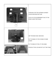
CHECKING THE TWO SCREWS ON REAR COVER WHETHER SETTLED LOCK UP 4*PCS SCREWS(M4*10-B) TO THE REAR COVER FOR FIXING GET THE BASE AND CHECKING PUT THE BASE TO THE STAND OF REAR COVER PUT THE BAG OF TOOL TO THE BASE STAND UP THE LCD AND PUT OUT THE FOAM
CHECKING THE TWO SCREWS ON REAR COVER WHETHER SETTLED LOCK UP 4*PCS SCREWS(M4*10-B) TO THE REAR COVER FOR FIXING GET THE BASE AND CHECKING PUT THE BASE TO THE STAND OF REAR COVER PUT THE BAG OF TOOL TO THE BASE STAND UP THE LCD AND PUT OUT THE FOAM
X241W Service Guide
Page 57
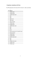
Proprietary connecting of DVI box The PIN assignment of the 24 pin DVI-D connector / cable is as follows: PIN Signal 1 TMDS data22 TMDS data2+ 3 TMDS data2 shield 4 NC 5 NC 6 DDC clock 7 DDC data 8 Not connected 9 TMDS data110 TMDS data1+ 11 TMDS data1 shield 12 NC 13 NC 14 +5V 15 Ground (return for +5 V and H/V sync) 16 Hot plug detect 17 TMDS data018 TMDS data0+ 19 TMDS data0 shield 20 NC 21 NC 22 TMDS clock shield 23 TMDS clock+ 24 TMDS clock- - 57 -
Proprietary connecting of DVI box The PIN assignment of the 24 pin DVI-D connector / cable is as follows: PIN Signal 1 TMDS data22 TMDS data2+ 3 TMDS data2 shield 4 NC 5 NC 6 DDC clock 7 DDC data 8 Not connected 9 TMDS data110 TMDS data1+ 11 TMDS data1 shield 12 NC 13 NC 14 +5V 15 Ground (return for +5 V and H/V sync) 16 Hot plug detect 17 TMDS data018 TMDS data0+ 19 TMDS data0 shield 20 NC 21 NC 22 TMDS clock shield 23 TMDS clock+ 24 TMDS clock- - 57 -
X241W Service Guide
Page 58
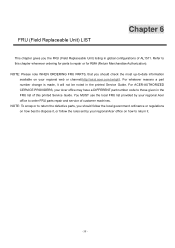
... a part number change is made, it . - 58 - You MUST use the local FRU list provided by your regional Acer office on your regional Acer office to order FRU parts repair and service of this chapter whenever ordering for RMA (Return Merchandise Authorization). FRU (Field Replaceable Unit) LIST Chapter 6 This chapter gives you the FRU (Field Replaceable Unit) listing in the printed Service Guide.
... a part number change is made, it . - 58 - You MUST use the local FRU list provided by your regional Acer office on your regional Acer office to order FRU parts repair and service of this chapter whenever ordering for RMA (Return Merchandise Authorization). FRU (Field Replaceable Unit) LIST Chapter 6 This chapter gives you the FRU (Field Replaceable Unit) listing in the printed Service Guide.
X241W Service Guide
Page 60
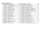
... IO NUT LI1 GP 19 MM40080BBW1 SCREW M4.0*8.0-B(NI,WASHER)GP 20 MM40060BBJ5 SCREW M4.0*6.0-B(NI)GP 21 MF25080PJB8 SCREW F2.5*8.0-P GP NUIT ITEM PART NUMBER PART DESCRIPTION 1 22 FBWDTB06015 PANEL HOOK WDTB GP 1 23 MF30100B008 SCREW F3.0*10.0-B BLACK GP 1 24 EBWDTB01013 INVERTOR SUPORT WDTB GP 1 25 FCWDTB03017 POWER MYLAR WDTB GP 1 26 DDL0TBBU001 CABLE MB-BUTTON(10P-8P,290MM)L0TB GP...
... IO NUT LI1 GP 19 MM40080BBW1 SCREW M4.0*8.0-B(NI,WASHER)GP 20 MM40060BBJ5 SCREW M4.0*6.0-B(NI)GP 21 MF25080PJB8 SCREW F2.5*8.0-P GP NUIT ITEM PART NUMBER PART DESCRIPTION 1 22 FBWDTB06015 PANEL HOOK WDTB GP 1 23 MF30100B008 SCREW F3.0*10.0-B BLACK GP 1 24 EBWDTB01013 INVERTOR SUPORT WDTB GP 1 25 FCWDTB03017 POWER MYLAR WDTB GP 1 26 DDL0TBBU001 CABLE MB-BUTTON(10P-8P,290MM)L0TB GP...
X241W Service Guide
Page 70
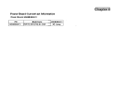
Power Board Current set Information Power Board AS08B360411 P/N Model Name AS08B360411 FSP112-3F01(T43) 90~240V AS08B360411 NO Jump Chapter 8
Power Board Current set Information Power Board AS08B360411 P/N Model Name AS08B360411 FSP112-3F01(T43) 90~240V AS08B360411 NO Jump Chapter 8

