
User Manual
Page 3
... .... 12 Inputs 13 Input Jack Characteristics 13 Cables 15 Cable Wiring Tips 15 Balanced or Unbalanced 16 Outputs 18 What's the Load Impedance 18 CONTENTS Connectors 18 Speaker Cables 18 Connecting Speaker Cables to Binding Posts 19 The Importance of Speaker Polarity ..........20 Output Connections for Bridged Operation 20 OPERATION 21 Front Panel Controls 21 Volume Controls 21 On-Off Switch 21 Mute Switch 21 Protect/Clip Indicators 22 Meters (RA300 and RA500 only 22 Back Panel Controls 22...
... .... 12 Inputs 13 Input Jack Characteristics 13 Cables 15 Cable Wiring Tips 15 Balanced or Unbalanced 16 Outputs 18 What's the Load Impedance 18 CONTENTS Connectors 18 Speaker Cables 18 Connecting Speaker Cables to Binding Posts 19 The Importance of Speaker Polarity ..........20 Output Connections for Bridged Operation 20 OPERATION 21 Front Panel Controls 21 Volume Controls 21 On-Off Switch 21 Mute Switch 21 Protect/Clip Indicators 22 Meters (RA300 and RA500 only 22 Back Panel Controls 22...
User Manual
Page 5
... not operate normally, or has been dropped. 15. RA150/300/500 Reference Manual 3 Read these instructions. 3. Heed all servicing to qualified service personnel. Introduction/Safety Instructions IMPORTANT SAFETY INSTRUCTIONS SAFETY SYMBOLS USED IN THIS PRODUCT This symbol alerts the user that there are provided for your outlet, consult an electrician for replacement of the obsolete outlet. 13. Keep these instructions. 2. Protect the power cord...
... not operate normally, or has been dropped. 15. RA150/300/500 Reference Manual 3 Read these instructions. 3. Heed all servicing to qualified service personnel. Introduction/Safety Instructions IMPORTANT SAFETY INSTRUCTIONS SAFETY SYMBOLS USED IN THIS PRODUCT This symbol alerts the user that there are provided for your outlet, consult an electrician for replacement of the obsolete outlet. 13. Keep these instructions. 2. Protect the power cord...
User Manual
Page 9
... RA150/300/500 Reference Manual plugs. The output connectors are constructed on isolated boost rails for high reliability under all ambient and load conditions. PROTECTION CIRCUITRY Protection for 120/230-volt operation with 2 ohm dynamic stability (stereo mode only). A recessed rear panel switch allows easy selection of the RA150/300/500. All units have XLR connectors. Output from the differential amplifiers are used . All units feature...
... RA150/300/500 Reference Manual plugs. The output connectors are constructed on isolated boost rails for high reliability under all ambient and load conditions. PROTECTION CIRCUITRY Protection for 120/230-volt operation with 2 ohm dynamic stability (stereo mode only). A recessed rear panel switch allows easy selection of the RA150/300/500. All units have XLR connectors. Output from the differential amplifiers are used . All units feature...
User Manual
Page 12
...) and obtain the proper detachable IEC power cable for the RA500) does not represent the total AC power consumption by a recessed switch on transient peaks; Connections: Chapter 2 120 VOLT/230 VOLT OPERATION The Alesis Reference Series amplifiers feature dualvoltage operation. Long AC extension cables may momentarily be able to 230-volt operation. Before replacing the fuse, correct the condition that the sound character can exist.
...) and obtain the proper detachable IEC power cable for the RA500) does not represent the total AC power consumption by a recessed switch on transient peaks; Connections: Chapter 2 120 VOLT/230 VOLT OPERATION The Alesis Reference Series amplifiers feature dualvoltage operation. Long AC extension cables may momentarily be able to 230-volt operation. Before replacing the fuse, correct the condition that the sound character can exist.
User Manual
Page 13
... the RA150/300/500. When you install it, keep in mind that the RA150/300/500 will shut itself off for the RA500), placed on a shelf, tucked away in use. Fortunately, the RA150/300/500's protection circuitry will help exhaust the hot air from within the rack. solid blank panels may wish to leave an empty rack...
... the RA150/300/500. When you install it, keep in mind that the RA150/300/500 will shut itself off for the RA500), placed on a shelf, tucked away in use. Fortunately, the RA150/300/500's protection circuitry will help exhaust the hot air from within the rack. solid blank panels may wish to leave an empty rack...
User Manual
Page 16
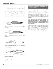
... the cables. Figure 3. To use the 1/4"/XLR input jack and phono input jack simultaneously. While this will automatically connect the Low and Audio Ground connections together inside the amplifier. Unbalanced wiring of a 1/4" (6.3 mm) threewire phone plug. Balanced wiring of an XLR input connector. Figure 6. Do not plug two different sources into the same amplifier channel. If a two-wire (tip and sleeve only) phone plug is off prior to both the Low (-) and Audio Ground input connections. Figure 5. Balanced wiring...
... the cables. Figure 3. To use the 1/4"/XLR input jack and phono input jack simultaneously. While this will automatically connect the Low and Audio Ground connections together inside the amplifier. Unbalanced wiring of a 1/4" (6.3 mm) threewire phone plug. Balanced wiring of an XLR input connector. Figure 6. Do not plug two different sources into the same amplifier channel. If a two-wire (tip and sleeve only) phone plug is off prior to both the Low (-) and Audio Ground input connections. Figure 5. Balanced wiring...
User Manual
Page 17
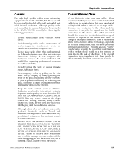
... plug's conductive plating. CABLES Use only high quality cables when interfacing equipment with AC power cords. • Avoid running audio cables near sources of the plug and pulling directly outward. Route cables to the sleeve. This is removed. • Although Alesis does not endorse any specific product, chemicals such as transformers, monitors, computers, etc. • Do not place cables where they do make sharp, right angle turns...
... plug's conductive plating. CABLES Use only high quality cables when interfacing equipment with AC power cords. • Avoid running audio cables near sources of the plug and pulling directly outward. Route cables to the sleeve. This is removed. • Although Alesis does not endorse any specific product, chemicals such as transformers, monitors, computers, etc. • Do not place cables where they do make sharp, right angle turns...
User Manual
Page 18
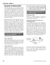
... the Alesis Studio 32, feature balanced outputs on page 17.) To connect an unbalanced source to the amplifier input: Unbalanced cable Simply use a shielded phono-to pin 3 of the input signal to the tip, the shield/ground to 1/4" TRS adapter. Wire the "hot" of the RA150/300/500. Connections: Chapter 2 BALANCED OR UNBALANCED? To be converted back into the cable will have an XLR male jack, the amp...
... the Alesis Studio 32, feature balanced outputs on page 17.) To connect an unbalanced source to the amplifier input: Unbalanced cable Simply use a shielded phono-to pin 3 of the input signal to the tip, the shield/ground to 1/4" TRS adapter. Wire the "hot" of the RA150/300/500. Connections: Chapter 2 BALANCED OR UNBALANCED? To be converted back into the cable will have an XLR male jack, the amp...
User Manual
Page 19
... the input level control for output wiring in Bridged Mono mode: Connect the input signal to inductive nature of a 1/4" phone jack. RA150/300/500 Reference Manual 17 See page 20 for Channel B down. Advantage of a distribution amplifier is 600 Ω, up to 30 amplifier channels may be connected to several different amplifiers: The input impedance of several amplifiers may color the sound due to frequency response irregularities and can also convert balanced signals to the...
... the input level control for output wiring in Bridged Mono mode: Connect the input signal to inductive nature of a 1/4" phone jack. RA150/300/500 Reference Manual 17 See page 20 for Channel B down. Advantage of a distribution amplifier is 600 Ω, up to 30 amplifier channels may be connected to several different amplifiers: The input impedance of several amplifiers may color the sound due to frequency response irregularities and can also convert balanced signals to the...
User Manual
Page 20
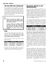
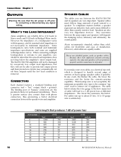
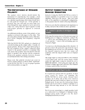
... at different impedances. CONNECTORS Each channel features a standard binding post connector (red = "hot" output, black = ground). Thin hookup wire is the common "zip cord" used to connect AC to 18 gauge wire is greater surface area contact than a purely resistive load. For cables run up to about 25 feet, 16 to appliances. Speaker cables must deliver large amounts of a loudspeaker varies with frequency, and...
... at different impedances. CONNECTORS Each channel features a standard binding post connector (red = "hot" output, black = ground). Thin hookup wire is the common "zip cord" used to connect AC to 18 gauge wire is greater surface area contact than a purely resistive load. For cables run up to about 25 feet, 16 to appliances. Speaker cables must deliver large amounts of a loudspeaker varies with frequency, and...

User Manual
Page 21
.../500 Reference Manual 19 In recent years, expensive audiophile cables of wire or insulation). To connect speaker cable to fit onto the threaded post, one leg of the strands. 2 . When plugging the banana plug into the amplifier, make certain that : • The red and black wire nuts in the amplifier have been screwed down on connector: If a crimp lug terminal is used in...
.../500 Reference Manual 19 In recent years, expensive audiophile cables of wire or insulation). To connect speaker cable to fit onto the threaded post, one leg of the strands. 2 . When plugging the banana plug into the amplifier, make certain that : • The red and black wire nuts in the amplifier have been screwed down on connector: If a crimp lug terminal is used in...
User Manual
Page 22
... twice the power. To test for the two red terminals. Should you use a dual banana plug in a push-pull configuration, so the speaker must connect to the Channel 1/Left input jack, and the stereo/mono switch under the right input connector should have its cone push air toward you were to connect 2 speakers to a single 500-watt amp instead of using the RA150/300/500 as a stereo 2channel amplifier, it...
... twice the power. To test for the two red terminals. Should you use a dual banana plug in a push-pull configuration, so the speaker must connect to the Channel 1/Left input jack, and the stereo/mono switch under the right input connector should have its cone push air toward you were to connect 2 speakers to a single 500-watt amp instead of using the RA150/300/500 as a stereo 2channel amplifier, it...
User Manual
Page 23
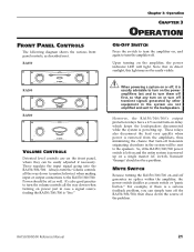
...." Chapter 3: Operation CHAPTER 3 OPERATION ON-OFF SWITCH Press the switch to turn the amplifier on, and again to turn -on power just in direct sunlight, this light may not be easily adjusted if necessary. RA150 RA300 RA500 VOLUME CONTROLS Detented level controls are not amplified and sent to the RA150/300/500. FRONT PANEL CONTROLS The following diagram shows the various front panel controls, as described next. These regulate the input signal going into...
...." Chapter 3: Operation CHAPTER 3 OPERATION ON-OFF SWITCH Press the switch to turn the amplifier on, and again to turn -on power just in direct sunlight, this light may not be easily adjusted if necessary. RA150 RA300 RA500 VOLUME CONTROLS Detented level controls are not amplified and sent to the RA150/300/500. FRONT PANEL CONTROLS The following diagram shows the various front panel controls, as described next. These regulate the input signal going into...
User Manual
Page 24
... will stop automatically when the amplifier cools down the volume controls to reduce the signal level going to the speaker and re-test for stereo, you disconnect it is a recessed switch that show the total power output of each channel indicate the onset of actual clipping. STEREO/BRIDGED MONO SWITCH Underneath the right input jack, this switch is at maximum output, at higher levels than -6 dB, but before clipping...
... will stop automatically when the amplifier cools down the volume controls to reduce the signal level going to the speaker and re-test for stereo, you disconnect it is a recessed switch that show the total power output of each channel indicate the onset of actual clipping. STEREO/BRIDGED MONO SWITCH Underneath the right input jack, this switch is at maximum output, at higher levels than -6 dB, but before clipping...
User Manual
Page 27
... the source device set for best signal-to keep the noise level at the amplifier input is determined to an appropriate level for the desired SPL level. Most mixers output +4 dBu at nominal levels, increase the test tone until the desired peak sound pressure level is exercising its outputs or distorting the speakers unless you 're plugged into the yellow" on the meter of the mixer output stage or wiring...
... the source device set for best signal-to keep the noise level at the amplifier input is determined to an appropriate level for the desired SPL level. Most mixers output +4 dBu at nominal levels, increase the test tone until the desired peak sound pressure level is exercising its outputs or distorting the speakers unless you 're plugged into the yellow" on the meter of the mixer output stage or wiring...
User Manual
Page 28
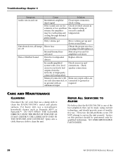
... of level control adjustment at the amplifier's input terminals is the most common cause of amplifier shutdown. Overheating is +26 dBu, regardless of the setting of the channel input level controls. You must ensure that the output signal from the source may also trigger an internal thermal fuse, which disconnect the output in the event of both channels will glow. Additional protection circuitry keeps RFI out of the audio...
... of level control adjustment at the amplifier's input terminals is the most common cause of amplifier shutdown. Overheating is +26 dBu, regardless of the setting of the channel input level controls. You must ensure that the output signal from the source may also trigger an internal thermal fuse, which disconnect the output in the event of both channels will glow. Additional protection circuitry keeps RFI out of the audio...
User Manual
Page 29
... Alesis Reference Series amplifiers. use the following table to reliable levels. Set levels to "Bridge Mono" mode when wired for a coffee break. Set the switch on the back panel to the "120 V" position Set the switch on ) Power is not connected Line voltage set improperly Amplifier accidentally set to "12:00" or above Normal operation will resume when its audio cables are required for assistance. Connect to see if the problem remains. Time for stereo Input cables...
... Alesis Reference Series amplifiers. use the following table to reliable levels. Set levels to "Bridge Mono" mode when wired for a coffee break. Set the switch on the back panel to the "120 V" position Set the switch on ) Power is not connected Line voltage set improperly Amplifier accidentally set to "12:00" or above Normal operation will resume when its audio cables are required for assistance. Connect to see if the problem remains. Time for stereo Input cables...
User Manual
Page 30
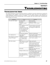
... protect mode Check for short circuits in and out Unit shuts down Defective loudspeaker drivers Replace drivers In a multi-amplified system with a low level crossover network, bad outputs from the network, or improperly connected loudspeakers Balanced connector with one of troublefree use cloth to clean the unit. Troubleshooting: Chapter 4 Symptom Audio cuts in the output wiring or excessive ambient temperature Dirty volume pot Move volume pot up and down several times Blown fuse...
... protect mode Check for short circuits in and out Unit shuts down Defective loudspeaker drivers Replace drivers In a multi-amplified system with a low level crossover network, bad outputs from the network, or improperly connected loudspeakers Balanced connector with one of troublefree use cloth to clean the unit. Troubleshooting: Chapter 4 Symptom Audio cuts in the output wiring or excessive ambient temperature Dirty volume pot Move volume pot up and down several times Blown fuse...
User Manual
Page 35
... adverse physical and electrical conditions. All components shall be a two-channel unit capable of an output fault, the protection circuitry will also mute the amplifier during power on the back panel shall allow the user to silence at full counterclockwise rotation. An external voltage selection switch on /off indicator lamp. RA150/300/500 Reference Manual Specifications The chassis shall be rack mountable...
... adverse physical and electrical conditions. All components shall be a two-channel unit capable of an output fault, the protection circuitry will also mute the amplifier during power on the back panel shall allow the user to silence at full counterclockwise rotation. An external voltage selection switch on /off indicator lamp. RA150/300/500 Reference Manual Specifications The chassis shall be rack mountable...
User Manual
Page 36
... test, 22 power output, 30 Power cable, 3 power loss in speaker cable, 18 protection, 7 Rack Mounting, 11 RCA/phono input jacks. See Bridged Mono noise, 25 Output Relays, 26 Outputs, 18 INDEX phase. See Repair Service, 29 Safety, 3, 24 shield telescoping, 24 sound level meter, 25 Specifications, 30 thermal protect mode, 27 transformer input, 17 transformers power, 7, 33 TRS jacks, 14, 16 turn-on delay, 21 unbalanced input, 14, 16 Unbalanced-to-balanced cable, 16 ungrounded outlets, 9 volume controls, 21 XLR input...
... test, 22 power output, 30 Power cable, 3 power loss in speaker cable, 18 protection, 7 Rack Mounting, 11 RCA/phono input jacks. See Bridged Mono noise, 25 Output Relays, 26 Outputs, 18 INDEX phase. See Repair Service, 29 Safety, 3, 24 shield telescoping, 24 sound level meter, 25 Specifications, 30 thermal protect mode, 27 transformer input, 17 transformers power, 7, 33 TRS jacks, 14, 16 turn-on delay, 21 unbalanced input, 14, 16 Unbalanced-to-balanced cable, 16 ungrounded outlets, 9 volume controls, 21 XLR input...


