Operating Instructions
Page 1
... München, Germany Phone 089-32 42 640 ALPINE ELECTRONICS OF U.K., LTD. Phone 0870-33 33 763 ALPINE ELECTRONICS FRANCE S.A.R.L. (RCS PONTOISE B 338 101 280) 98, Rue de la Belle Etoile, Z.I. Marine Remote Commander System MC10 • Operating Instructions Please read before using this ...equipment. Portal de Gamarra 36, Pabellón, 32 01013 Vitoria (Alava)-APDO 133, Spain Phone 945-283588 ALPINE ELECTRONICS (BENELUX) GmbH Leuvensesteenweg 510-B6, 1930 Zaventem,...
... München, Germany Phone 089-32 42 640 ALPINE ELECTRONICS OF U.K., LTD. Phone 0870-33 33 763 ALPINE ELECTRONICS FRANCE S.A.R.L. (RCS PONTOISE B 338 101 280) 98, Rue de la Belle Etoile, Z.I. Marine Remote Commander System MC10 • Operating Instructions Please read before using this ...equipment. Portal de Gamarra 36, Pabellón, 32 01013 Vitoria (Alava)-APDO 133, Spain Phone 945-283588 ALPINE ELECTRONICS (BENELUX) GmbH Leuvensesteenweg 510-B6, 1930 Zaventem,...
Operating Instructions
Page 2
... subject to heed them can be performed after coming to do so may result in a safe location before turning your Alpine dealer or the nearest Alpine Service Station for other than its designed application may result in an accident. KEEP SMALL OBJECTS SUCH AS BOLTS OR SCREWS...in accident or fire. Use for servicing. HALT USE IMMEDIATELY IF A PROBLEM APPEARS. Excessive volume levels that requires your authorized Alpine dealer or the nearest Alpine Service Center for periodic cleaning of the product. DO NOT DISASSEMBLE OR ALTER. Anything else has the chance of the boat ...
... subject to heed them can be performed after coming to do so may result in a safe location before turning your Alpine dealer or the nearest Alpine Service Station for other than its designed application may result in an accident. KEEP SMALL OBJECTS SUCH AS BOLTS OR SCREWS...in accident or fire. Use for servicing. HALT USE IMMEDIATELY IF A PROBLEM APPEARS. Excessive volume levels that requires your authorized Alpine dealer or the nearest Alpine Service Center for periodic cleaning of the product. DO NOT DISASSEMBLE OR ALTER. Anything else has the chance of the boat ...

Operating Instructions
Page 3
Basic Operation Installation MC10 Display Unit Optional Add-on Commander GND +12V 2.4GHz Wireless 2.4GHz Wireless MC10 Transceiver Unit MC1 GND +12V To 10P Sub Display Connector To Steering Wheel Jack GND +12V BLACK : connect to Ground (GND) RED : connect to 12V(+): ACC (switched) Optional RUE-M1RF 333MHz Wireless GND +12V BLACK : connect to Ground (GND) YELLOW : connect to 12V(+): ACC (switched) IDA-X100M OR CDA-9886M 3 291031_MC10_OM_En_R1.indd 3 5/29/09 7:18:04 PM
Basic Operation Installation MC10 Display Unit Optional Add-on Commander GND +12V 2.4GHz Wireless 2.4GHz Wireless MC10 Transceiver Unit MC1 GND +12V To 10P Sub Display Connector To Steering Wheel Jack GND +12V BLACK : connect to Ground (GND) RED : connect to 12V(+): ACC (switched) Optional RUE-M1RF 333MHz Wireless GND +12V BLACK : connect to Ground (GND) YELLOW : connect to 12V(+): ACC (switched) IDA-X100M OR CDA-9886M 3 291031_MC10_OM_En_R1.indd 3 5/29/09 7:18:04 PM

Operating Instructions
Page 4
...4 291031_MC10_OM_En_R1.indd 4 5/29/09 7:18:10 PM BL DISPLAY Turns LCD backlighting ON or OFF 6. Program Menu Enter Program Mode MC10 Display unit Program Menu Options 1. CONTRAST Sets brightness or dimness of serial numbers: 00001 to 99999 2. BL KEYPAD Turns keypad button backlighting... ON or OFF 7. SIGNAL STATUS Wireless signal connection status between a display unit and the closest display or transceiver unit in the MC10 wireless system * Range of strength: [ to DEGREES F or DEGREES C 8. ID NUMBER This is the serial number of the display unit...
...4 291031_MC10_OM_En_R1.indd 4 5/29/09 7:18:10 PM BL DISPLAY Turns LCD backlighting ON or OFF 6. Program Menu Enter Program Mode MC10 Display unit Program Menu Options 1. CONTRAST Sets brightness or dimness of serial numbers: 00001 to 99999 2. BL KEYPAD Turns keypad button backlighting... ON or OFF 7. SIGNAL STATUS Wireless signal connection status between a display unit and the closest display or transceiver unit in the MC10 wireless system * Range of strength: [ to DEGREES F or DEGREES C 8. ID NUMBER This is the serial number of the display unit...
Operating Instructions
Page 5
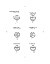
Press VOL + or VOL - to save new CONTRAST value 3. Press ENT to adjust the current CONTRAST value 2. Press ENT to exit Program Mode 5 291031_MC10_OM_En_R1.indd 5 5/29/09 7:18:10 PM Enter Program Mode 4. Press ESC to program new CONTRAST value 6. Press VOL + or VOL - Program Mode Example 1. until CONTRAST shows on top line of display 5.
Press VOL + or VOL - to save new CONTRAST value 3. Press ENT to adjust the current CONTRAST value 2. Press ENT to exit Program Mode 5 291031_MC10_OM_En_R1.indd 5 5/29/09 7:18:10 PM Enter Program Mode 4. Press ESC to program new CONTRAST value 6. Press VOL + or VOL - Program Mode Example 1. until CONTRAST shows on top line of display 5.

Operating Instructions
Page 6
...18:11 PM On marine radio, press SEEK UP ( ) once 7. Press ESC to finish pairing operation and save new settings 9. Turn off the existing MC10 system, then turn on commander (see Installation) 3. Press ENT to exit Program Menu 10. Power on Commander Pairing Procedure 1. Found Radio will appear below ...ADD MC1 when add-on commander is ready to the pairing screen in the program menu with MC10 system * ADD MC1 Found Radio 6. PRESS ENTER will appear on the display below ADD MC1 on the display ADD MC1 MC1 Paring Screen ...
...18:11 PM On marine radio, press SEEK UP ( ) once 7. Press ESC to finish pairing operation and save new settings 9. Turn off the existing MC10 system, then turn on commander (see Installation) 3. Press ENT to exit Program Menu 10. Power on Commander Pairing Procedure 1. Found Radio will appear below ...ADD MC1 when add-on commander is ready to the pairing screen in the program menu with MC10 system * ADD MC1 Found Radio 6. PRESS ENTER will appear on the display below ADD MC1 on the display ADD MC1 MC1 Paring Screen ...

Operating Instructions
Page 7
Example Systems Transceiver APN Marine Head Unit 2.4GHz Wireless MC10 Marine Commander System Transceiver 2.4GHz Wireless APN Marine Head Unit 2.4GHz Wireless MC1 Add on MC10 Marine Commander System with MC1 Add on Commander 7 291031_MC10_OM_En_R1.indd 7 5/29/09 7:18:11 PM
Example Systems Transceiver APN Marine Head Unit 2.4GHz Wireless MC10 Marine Commander System Transceiver 2.4GHz Wireless APN Marine Head Unit 2.4GHz Wireless MC1 Add on MC10 Marine Commander System with MC1 Add on Commander 7 291031_MC10_OM_En_R1.indd 7 5/29/09 7:18:11 PM

Operating Instructions
Page 8
... then press ENT button 5. Power on Commander Pairing Procedure) 6. Connect power and ground wires of new MC10 display unit 3. MC10 Display Unit Re-Pairing Procedure * To pair an MC10 display unit with a different MC10 system than the one it was purchased with (just like in step 3 of the previous section (MC1... Add-on the MC10 system that you want to add the additional MC10 display unit to 2. MC10 display unit will reset itself (including factory default settings) and display will show ADD MC1 like adding an ...
... then press ENT button 5. Power on Commander Pairing Procedure) 6. Connect power and ground wires of new MC10 display unit 3. MC10 Display Unit Re-Pairing Procedure * To pair an MC10 display unit with a different MC10 system than the one it was purchased with (just like in step 3 of the previous section (MC1... Add-on the MC10 system that you want to add the additional MC10 display unit to 2. MC10 display unit will reset itself (including factory default settings) and display will show ADD MC1 like adding an ...