Operating Instructions
Page 1
...-725 1315 Printed in China 291031_MC10_OM_En_R1.indd 1 5/29/09 7:18:03 PM Phone 0870-33 33 763 ALPINE ELECTRONICS FRANCE S.A.R.L. (RCS PONTOISE B 338 101 280) 98, Rue de la Belle Etoile, Z.I. ALPINE House Fletchamstead Highway, Coventry CCV4 9TW, U.K. Marine Remote Commander System MC10 • Operating Instructions Please read before using this equipment. Colombo 8, 20090 Trezzano Sul Naviglio (MI), Italy...
...-725 1315 Printed in China 291031_MC10_OM_En_R1.indd 1 5/29/09 7:18:03 PM Phone 0870-33 33 763 ALPINE ELECTRONICS FRANCE S.A.R.L. (RCS PONTOISE B 338 101 280) 98, Rue de la Belle Etoile, Z.I. ALPINE House Fletchamstead Highway, Coventry CCV4 9TW, U.K. Marine Remote Commander System MC10 • Operating Instructions Please read before using this equipment. Colombo 8, 20090 Trezzano Sul Naviglio (MI), Italy...
Operating Instructions
Page 2
... PM CAUTION This symbol means important instructions. Return it to your authorized Alpine dealer or the nearest Alpine Service Center for compliance could void the user's authority to the following two conditions: (1) This device may not cause harmful interference, and (2) This device must accept any interference received, including interference that may distract the driver from looking ahead of dissolving...
... PM CAUTION This symbol means important instructions. Return it to your authorized Alpine dealer or the nearest Alpine Service Center for compliance could void the user's authority to the following two conditions: (1) This device may not cause harmful interference, and (2) This device must accept any interference received, including interference that may distract the driver from looking ahead of dissolving...

Operating Instructions
Page 3
Basic Operation Installation MC10 Display Unit Optional Add-on Commander GND +12V 2.4GHz Wireless 2.4GHz Wireless MC10 Transceiver Unit MC1 GND +12V To 10P Sub Display Connector To Steering Wheel Jack GND +12V BLACK : connect to Ground (GND) RED : connect to 12V(+): ACC (switched) Optional RUE-M1RF 333MHz Wireless GND +12V BLACK : connect to Ground (GND) YELLOW : connect to 12V(+): ACC (switched) IDA-X100M OR CDA-9886M 3 291031_MC10_OM_En_R1.indd 3 5/29/09 7:18:04 PM
Basic Operation Installation MC10 Display Unit Optional Add-on Commander GND +12V 2.4GHz Wireless 2.4GHz Wireless MC10 Transceiver Unit MC1 GND +12V To 10P Sub Display Connector To Steering Wheel Jack GND +12V BLACK : connect to Ground (GND) RED : connect to 12V(+): ACC (switched) Optional RUE-M1RF 333MHz Wireless GND +12V BLACK : connect to Ground (GND) YELLOW : connect to 12V(+): ACC (switched) IDA-X100M OR CDA-9886M 3 291031_MC10_OM_En_R1.indd 3 5/29/09 7:18:04 PM

Operating Instructions
Page 4
... KEYPAD Turns keypad button backlighting ON or OFF 7. RESET MC1 also restores factory default setting * Note: Bold indicates default menu selection for pairing or re-pairing any MC1 or MC10 display units with any existing MC10 system. SIGNAL STATUS Wireless signal connection status between a display unit and the closest display or transceiver unit in the MC10 wireless system * Range of LCD display characters * Values: [5, 4, 3, 2, 1, 0] 5. Program Menu Enter Program Mode MC10 Display unit Program Menu Options 1. BL DISPLAY Turns LCD backlighting...
... KEYPAD Turns keypad button backlighting ON or OFF 7. RESET MC1 also restores factory default setting * Note: Bold indicates default menu selection for pairing or re-pairing any MC1 or MC10 display units with any existing MC10 system. SIGNAL STATUS Wireless signal connection status between a display unit and the closest display or transceiver unit in the MC10 wireless system * Range of LCD display characters * Values: [5, 4, 3, 2, 1, 0] 5. Program Menu Enter Program Mode MC10 Display unit Program Menu Options 1. BL DISPLAY Turns LCD backlighting...
Operating Instructions
Page 5
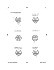
Press ESC to program new CONTRAST value 6. Press ENT to exit Program Mode 5 291031_MC10_OM_En_R1.indd 5 5/29/09 7:18:10 PM to save new CONTRAST value 3. Press ENT to adjust the current CONTRAST value 2. Press VOL + or VOL - until CONTRAST shows on top line of display 5. Program Mode Example 1. Press VOL + or VOL - Enter Program Mode 4.
Press ESC to program new CONTRAST value 6. Press ENT to exit Program Mode 5 291031_MC10_OM_En_R1.indd 5 5/29/09 7:18:10 PM to save new CONTRAST value 3. Press ENT to adjust the current CONTRAST value 2. Press VOL + or VOL - until CONTRAST shows on top line of display 5. Program Mode Example 1. Press VOL + or VOL - Enter Program Mode 4.

Operating Instructions
Page 6
... pairing operation and save new settings 9. MC1 Add-on the display ADD MC1 PRESS ENTER 8. Power on . Connect power and ground wires of MC10 system range (typical ~ 40 feet/12 m) 6 291031_MC10_OM_En_R1.indd 6 5/29/09 7:18:11 PM Pairing procedure is ready to the pairing screen in the program menu with MC10 system * ADD MC1 Found Radio 6. MC1 add-on commander display will appear on the display below ADD MC1 on Commander Pairing...
... pairing operation and save new settings 9. MC1 Add-on the display ADD MC1 PRESS ENTER 8. Power on . Connect power and ground wires of MC10 system range (typical ~ 40 feet/12 m) 6 291031_MC10_OM_En_R1.indd 6 5/29/09 7:18:11 PM Pairing procedure is ready to the pairing screen in the program menu with MC10 system * ADD MC1 Found Radio 6. MC1 add-on commander display will appear on the display below ADD MC1 on Commander Pairing...

Operating Instructions
Page 7
Example Systems Transceiver APN Marine Head Unit 2.4GHz Wireless MC10 Marine Commander System Transceiver 2.4GHz Wireless APN Marine Head Unit 2.4GHz Wireless MC1 Add on MC10 Marine Commander System with MC1 Add on Commander 7 291031_MC10_OM_En_R1.indd 7 5/29/09 7:18:11 PM
Example Systems Transceiver APN Marine Head Unit 2.4GHz Wireless MC10 Marine Commander System Transceiver 2.4GHz Wireless APN Marine Head Unit 2.4GHz Wireless MC1 Add on MC10 Marine Commander System with MC1 Add on Commander 7 291031_MC10_OM_En_R1.indd 7 5/29/09 7:18:11 PM

Operating Instructions
Page 8
... 20 seconds, then enter the Program Menu (see Program Menu Example) 4. Connect power and ground wires of the previous section to the RESET MC1 option, then press ENT button 5. MC10 display unit will reset itself (including factory default settings) and display will show ADD MC1 like adding an MC1 Commander) follow the instructions below: 1. MC10 Display Unit Re-Pairing Procedure * To pair an MC10 display unit with a different MC10 system than the one...
... 20 seconds, then enter the Program Menu (see Program Menu Example) 4. Connect power and ground wires of the previous section to the RESET MC1 option, then press ENT button 5. MC10 display unit will reset itself (including factory default settings) and display will show ADD MC1 like adding an MC1 Commander) follow the instructions below: 1. MC10 Display Unit Re-Pairing Procedure * To pair an MC10 display unit with a different MC10 system than the one...


