Owners Manual
Page 5
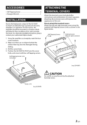
...S2-A36F/S2-A55V over the screw holes, and secure with four self-tapping screws. Make sure there are no objects behind the surface that may become damaged during drilling. 3. Attaching the terminal covers will allow for free circulation of the unit. Holes (× 4) (e.g. For alternate installation locations, please contact your authorized Alpine...4) (included) ATTACHING THE TERMINAL COVERS Attach the terminal covers (included) after connections and confirmation of the S2-A36F/ S2-A55V considerable heat is produced when the amplifier is in the figure below. How to the high power ...
...S2-A36F/S2-A55V over the screw holes, and secure with four self-tapping screws. Make sure there are no objects behind the surface that may become damaged during drilling. 3. Attaching the terminal covers will allow for free circulation of the unit. Holes (× 4) (e.g. For alternate installation locations, please contact your authorized Alpine...4) (included) ATTACHING THE TERMINAL COVERS Attach the terminal covers (included) after connections and confirmation of the S2-A36F/ S2-A55V considerable heat is produced when the amplifier is in the figure below. How to the high power ...
Owners Manual
Page 10
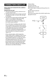
... the tape or CD Mode). Make sure the switch is accessible by the driver. CONNECTION CHECK LIST Please check your S2-A36F/S2-A55V must be installed in-line on the S2-A36F/S2-A55V turn-on lead. c. If this ignition tap. The head unit does not have a remote turn -on ...b. The head unit's power antenna lead is logic level output (+) 5 V, negative trigger (grounding type), or cannot sustain (+) 12 V when connected to other Alpine component's Remote Turn-On Leads SPST Switch (optional) Fuse (3 A) As close as the ignition switch is objectionable, a SPST (Single Pole, Single Throw) switch,...
... the tape or CD Mode). Make sure the switch is accessible by the driver. CONNECTION CHECK LIST Please check your S2-A36F/S2-A55V must be installed in-line on the S2-A36F/S2-A55V turn-on lead. c. If this ignition tap. The head unit does not have a remote turn -on ...b. The head unit's power antenna lead is logic level output (+) 5 V, negative trigger (grounding type), or cannot sustain (+) 12 V when connected to other Alpine component's Remote Turn-On Leads SPST Switch (optional) Fuse (3 A) As close as the ignition switch is objectionable, a SPST (Single Pole, Single Throw) switch,...
Owners Manual
Page 14
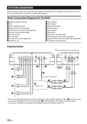
...Type Switch [LO] Remote Turn-On Lead Head Unit, etc. * If the connected head unit does not have any questions, contact the nearest Alpine dealer. SYSTEM DIAGRAMS Before making a connection, check the total number of impedance of the speaker connected to the Speaker Input Level System" (page... Cable ( ) (sold separately) RCA Input Jacks Pre-Out Jacks Remote Bass Control (optional) Head Unit, etc. Basic Connection Diagram for S2-A36F Speaker Output Terminals Fuse Power Supply Terminal Battery Lead (sold separately) Remote Turn-On Lead (sold separately) Ground Lead (sold separately).
...Type Switch [LO] Remote Turn-On Lead Head Unit, etc. * If the connected head unit does not have any questions, contact the nearest Alpine dealer. SYSTEM DIAGRAMS Before making a connection, check the total number of impedance of the speaker connected to the Speaker Input Level System" (page... Cable ( ) (sold separately) RCA Input Jacks Pre-Out Jacks Remote Bass Control (optional) Head Unit, etc. Basic Connection Diagram for S2-A36F Speaker Output Terminals Fuse Power Supply Terminal Battery Lead (sold separately) Remote Turn-On Lead (sold separately) Ground Lead (sold separately).


