
Owners Manual
Page 1
... läsa igenom denna användarhandledning. EN S2-A36F DE 4 CHANNEL POWER AMPLIFIER FR S2-A55V 4 CHANNEL + MONO POWER AMPLIFIER ES IT • OWNER'S MANUAL Please read before using this equipment. • BEDIENUNGSANLEITUNG Lesen Sie diese Bedienungsanleitung bitte vor Gebrauch des Gerätes. • MODE D'EMPLOI Veuillez lire avant d'utiliser cet appareil. • MANUAL DE OPERACIÓN Léalo antes de utilizar este...
... läsa igenom denna användarhandledning. EN S2-A36F DE 4 CHANNEL POWER AMPLIFIER FR S2-A55V 4 CHANNEL + MONO POWER AMPLIFIER ES IT • OWNER'S MANUAL Please read before using this equipment. • BEDIENUNGSANLEITUNG Lesen Sie diese Bedienungsanleitung bitte vor Gebrauch des Gerätes. • MODE D'EMPLOI Veuillez lire avant d'utiliser cet appareil. • MANUAL DE OPERACIÓN Léalo antes de utilizar este...
Owners Manual
Page 3
.... USE THIS PRODUCT FOR MOBILE 12V APPLICATIONS. Failure to do so may result in this manual. English CONTENTS WARNING 1 SERVICE CARE 2 ACCESSORIES 3 INSTALLATION 3 ATTACHING THE TERMINAL COVERS 3 CONNECTIONS 4 CONNECTION CHECK LIST 8 SWITCH SETTINGS 9 SYSTEM DIAGRAMS 12 SPECIFICATIONS 18 WARNING Points to Observe for Safe Usage Read this manual carefully before performing these functions. MAKE THE CORRECT CONNECTIONS. Arrange wiring and cables in fire or electric shock. They contain instructions...
.... USE THIS PRODUCT FOR MOBILE 12V APPLICATIONS. Failure to do so may result in this manual. English CONTENTS WARNING 1 SERVICE CARE 2 ACCESSORIES 3 INSTALLATION 3 ATTACHING THE TERMINAL COVERS 3 CONNECTIONS 4 CONNECTION CHECK LIST 8 SWITCH SETTINGS 9 SYSTEM DIAGRAMS 12 SPECIFICATIONS 18 WARNING Points to Observe for Safe Usage Read this manual carefully before performing these functions. MAKE THE CORRECT CONNECTIONS. Arrange wiring and cables in fire or electric shock. They contain instructions...

Owners Manual
Page 4
... result in accordance with high incidence of the hole. CAUTION This symbol means important instructions. Route the cables and wiring away from being cut by the metal edge of moisture or dust. SERVICE CARE IMPORTANT NOTICE This Amplifier has been type tested and found to comply with the limits for installations or ground connections. This equipment generates and uses radio frequency energy, and it...
... result in accordance with high incidence of the hole. CAUTION This symbol means important instructions. Route the cables and wiring away from being cut by the metal edge of moisture or dust. SERVICE CARE IMPORTANT NOTICE This Amplifier has been type tested and found to comply with the limits for installations or ground connections. This equipment generates and uses radio frequency energy, and it...
Owners Manual
Page 5
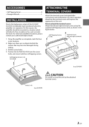
.... Self-Tapping Screws (× 4) (included) ATTACHING THE TERMINAL COVERS Attach the terminal covers (included) after connections and confirmation of correct operation. How to the high power output of the S2-A36F/ S2-A55V considerable heat is produced when the amplifier is in a location which will improve the appearance of the unit. For alternate installation locations, please contact your authorized Alpine dealer. 1. Using the amplifier as inside...
.... Self-Tapping Screws (× 4) (included) ATTACHING THE TERMINAL COVERS Attach the terminal covers (included) after connections and confirmation of correct operation. How to the high power output of the S2-A36F/ S2-A55V considerable heat is produced when the amplifier is in a location which will improve the appearance of the unit. For alternate installation locations, please contact your authorized Alpine dealer. 1. Using the amplifier as inside...
Owners Manual
Page 6
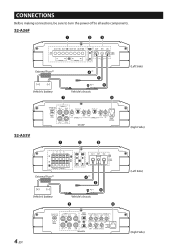
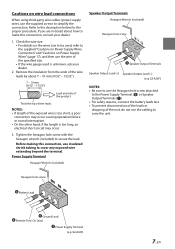
CONNECTIONS Before making connections, be sure to turn the power off to all audio components. S2-A36F External Fuse*2 Vehicle's battery *1 *3, 4 Vehicle's chassis (Left Side) S2-A55V (Right Side) External Fuse*2 Vehicle's battery *1 *3, 4 Vehicle's chassis (Left Side) 4-EN (Right Side)
CONNECTIONS Before making connections, be sure to turn the power off to all audio components. S2-A36F External Fuse*2 Vehicle's battery *1 *3, 4 Vehicle's chassis (Left Side) S2-A55V (Right Side) External Fuse*2 Vehicle's battery *1 *3, 4 Vehicle's chassis (Left Side) 4-EN (Right Side)

Owners Manual
Page 7
... on Power Supply Wires Connection" and "Cautions on the fuse capacity of this machine, see "Battery Lead ( )" (page 6). *3 Connect all equipment to the same ground point while keeping wire length as short as possible. *4 To securely connect the ground lead, use the wire of the specified size. *2 Be sure to add an External Fuse (e.g. For details on Power Supply Wires" (page 17), and then use an already installed screw. Fuse Block, Circuit...
... on Power Supply Wires Connection" and "Cautions on the fuse capacity of this machine, see "Battery Lead ( )" (page 6). *3 Connect all equipment to the same ground point while keeping wire length as short as possible. *4 To securely connect the ground lead, use the wire of the specified size. *2 Be sure to add an External Fuse (e.g. For details on Power Supply Wires" (page 17), and then use an already installed screw. Fuse Block, Circuit...

Owners Manual
Page 8
... prevent ground loops while keeping wire length as short as possible to adjust the output level remotely. In such a case, connect the remote turn -on lead is not to replace appropriate gain level setting between that point and the negative (-) terminal of the vehicle's battery. RCA Input Jacks Connect these jacks to the line out leads on lead to the remote turn -on lead, owing to the "REMOTE SENSING" function of the head unit to this unit...
... prevent ground loops while keeping wire length as short as possible to adjust the output level remotely. In such a case, connect the remote turn -on lead is not to replace appropriate gain level setting between that point and the negative (-) terminal of the vehicle's battery. RCA Input Jacks Connect these jacks to the line out leads on lead to the remote turn -on lead, owing to the "REMOTE SENSING" function of the head unit to this unit...
Owners Manual
Page 9
... proper procedure. Hexagon hole screw Battery Lead Ground Lead Remote Turn-On Lead Power Supply Terminal (e.g. Remove the insulation from the ends of the unit, do not use insulated shrink tubing to make this connection, use the cabling to simplify the connection. S2-A36F) NOTES: • Be sure to use the Hexagon hole screw attached to the Power Supply Terminal ( ) or Speaker Output Terminals ( ). • For safety reasons, connect the battery leads last. •...
... proper procedure. Hexagon hole screw Battery Lead Ground Lead Remote Turn-On Lead Power Supply Terminal (e.g. Remove the insulation from the ends of the unit, do not use insulated shrink tubing to make this connection, use the cabling to simplify the connection. S2-A36F) NOTES: • Be sure to use the Hexagon hole screw attached to the Power Supply Terminal ( ) or Speaker Output Terminals ( ). • For safety reasons, connect the battery leads last. •...
Owners Manual
Page 10
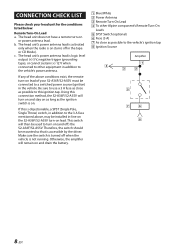
... vehicle. CONNECTION CHECK LIST Please check your S2-A36F/S2-A55V must be connected to this ignition tap. The head unit's power antenna lead is logic level output (+) 5 V, negative trigger (grounding type), or cannot sustain (+) 12 V when connected to other Alpine component's Remote Turn-On Leads SPST Switch (optional) Fuse (3 A) As close as possible to a switched power source (ignition) in the tape or CD Mode). Otherwise, the amplifier will turn on and stay on...
... vehicle. CONNECTION CHECK LIST Please check your S2-A36F/S2-A55V must be connected to this ignition tap. The head unit's power antenna lead is logic level output (+) 5 V, negative trigger (grounding type), or cannot sustain (+) 12 V when connected to other Alpine component's Remote Turn-On Leads SPST Switch (optional) Fuse (3 A) As close as possible to a switched power source (ignition) in the tape or CD Mode). Otherwise, the amplifier will turn on and stay on...
Owners Manual
Page 11
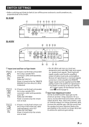
... the sound from the amplified output of radios, head units, and amplifiers. c) If input is turned on by the "REMOTE SENSING" function when DC offset is no longer distorted). Input Gain Adjustment Control Set the S2-A36F/S2-A55V input gain to achieve the optimum gain setting. 9-EN TURN-ON TYPE "REM": Power is via the head unit speaker line using an RCA extension cable (sold separately), set to "HI". Now, increase the amplifier gain until the output is via the head unit pre-out line using a speaker-RCA conversion cable (sold separately), set...
... the sound from the amplified output of radios, head units, and amplifiers. c) If input is turned on by the "REMOTE SENSING" function when DC offset is no longer distorted). Input Gain Adjustment Control Set the S2-A36F/S2-A55V input gain to achieve the optimum gain setting. 9-EN TURN-ON TYPE "REM": Power is via the head unit speaker line using an RCA extension cable (sold separately), set to "HI". Now, increase the amplifier gain until the output is via the head unit pre-out line using a speaker-RCA conversion cable (sold separately), set...
Owners Manual
Page 12
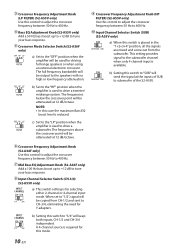
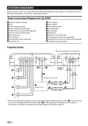
... point will be output to the speakers with no high or low frequency attenuation. Crossover Frequency Adjustment Knob (LP FILTER) (S2-A55V only) Use this control to adjust the crossover frequency between 50 Hz to 400 Hz. The frequencies below the crossover point will be copied from the subwoofer. This setting provides signal to the subwoofer channel when only 4 channel input is reduced. b) Set to "1/2", signal will keep both inputs, CH-1/2 and CH...
... point will be output to the speakers with no high or low frequency attenuation. Crossover Frequency Adjustment Knob (LP FILTER) (S2-A55V only) Use this control to adjust the crossover frequency between 50 Hz to 400 Hz. The frequencies below the crossover point will be copied from the subwoofer. This setting provides signal to the subwoofer channel when only 4 channel input is reduced. b) Set to "1/2", signal will keep both inputs, CH-1/2 and CH...
Owners Manual
Page 13
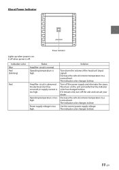
... volume of the head unit (input signal). Then turn off . The indicator color changes to a normal level. An electrical short has occurred, or supply current is too high. Power supply voltage is too high. Decrease the vehicle's interior temperature to blue. 11-EN Turn off when power is high. Decrease the vehicle's interior temperature to blue. Indication color Blue Red (blinking) Red Status Amplifier circuit is abnormal. The indicator color changes to a normal level. The indicator color changes to blue. Amplifier circuit...
... volume of the head unit (input signal). Then turn off . The indicator color changes to a normal level. An electrical short has occurred, or supply current is too high. Power supply voltage is too high. Decrease the vehicle's interior temperature to blue. 11-EN Turn off when power is high. Decrease the vehicle's interior temperature to blue. Indication color Blue Red (blinking) Red Status Amplifier circuit is abnormal. The indicator color changes to a normal level. The indicator color changes to blue. Amplifier circuit...
Owners Manual
Page 14
...Basic Connection Diagram for S2-A36F Speaker Output Terminals Fuse Power Supply Terminal Battery Lead (sold separately) Remote Turn-On Lead (sold separately) Ground Lead (sold separately). For details on Type Switch [LO] Remote Turn-On Lead Head Unit, etc. * If the connected head unit does not have a Speaker Output and RCA Extension Cable ( ) cannot be used, you have any questions, contact the nearest Alpine dealer. Front Output Rear Output Subwoofer Output Front Speakers Rear Speaker Subwoofer Dual Voice Coil Subwoofer RCA Extension Cable (sold separately) Speaker-RCA Conversion Cable...
...Basic Connection Diagram for S2-A36F Speaker Output Terminals Fuse Power Supply Terminal Battery Lead (sold separately) Remote Turn-On Lead (sold separately) Ground Lead (sold separately). For details on Type Switch [LO] Remote Turn-On Lead Head Unit, etc. * If the connected head unit does not have a Speaker Output and RCA Extension Cable ( ) cannot be used, you have any questions, contact the nearest Alpine dealer. Front Output Rear Output Subwoofer Output Front Speakers Rear Speaker Subwoofer Dual Voice Coil Subwoofer RCA Extension Cable (sold separately) Speaker-RCA Conversion Cable...
Owners Manual
Page 15
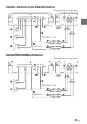
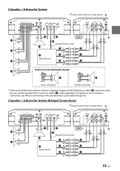
2 Speaker + Subwoofer System (Bridged Connections) Input Level and Turn-on Type Switch [LO] Remote Turn-On Lead Head Unit, etc. 2 Speaker System (Bridged Connections) Input Level and Turn-on Type Switch [LO] Remote Turn-On Lead Head Unit, etc. 13-EN
2 Speaker + Subwoofer System (Bridged Connections) Input Level and Turn-on Type Switch [LO] Remote Turn-On Lead Head Unit, etc. 2 Speaker System (Bridged Connections) Input Level and Turn-on Type Switch [LO] Remote Turn-On Lead Head Unit, etc. 13-EN
Owners Manual
Page 16
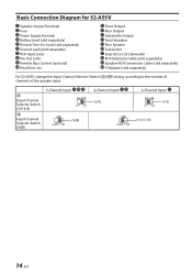
Basic Connection Diagram for S2-A55V Speaker Output Terminals Fuse Power Supply Terminal Battery Lead (sold separately) Remote Turn-On Lead (sold separately) Ground Lead (sold separately) For S2-A55V, change the Input Channel Selector Switch ( )/( ) setting according to the number of channels of the speaker input. 5-Channel Input: 4-Channel Input: 2-Channel Input: Input Channel [3/4] [1/2] Selector Switch (CH-3/4) Input Channel Selector Switch (SUB) [SUB] [1+2+3+4] 14-EN Front Output Rear Output Subwoofer Output Front Speakers Rear Speaker Subwoofer Dual Voice Coil Subwoofer RCA...
Basic Connection Diagram for S2-A55V Speaker Output Terminals Fuse Power Supply Terminal Battery Lead (sold separately) Remote Turn-On Lead (sold separately) Ground Lead (sold separately) For S2-A55V, change the Input Channel Selector Switch ( )/( ) setting according to the number of channels of the speaker input. 5-Channel Input: 4-Channel Input: 2-Channel Input: Input Channel [3/4] [1/2] Selector Switch (CH-3/4) Input Channel Selector Switch (SUB) [SUB] [1+2+3+4] 14-EN Front Output Rear Output Subwoofer Output Front Speakers Rear Speaker Subwoofer Dual Voice Coil Subwoofer RCA...
Owners Manual
Page 17
4 Speaker + Subwoofer System Input Level and Turn-on Type Switch [LO] Remote Turn-On Lead Head Unit, etc. 15-EN For details on how to make a connection, see "About Connecting to the Speaker Input Level System" (page 16). 2 Speaker + Subwoofer System (Bridged Connections) Input Level and Turn-on Type Switch [LO] Remote Turn-On Lead Head Unit, etc. Dual Voice Coil Subwoofer System Series connection Parallel connection * If the connected head unit does not have a Speaker Output and RCA Extension Cable ( ) cannot be used, you can use the Speaker-RCA Conversion Cable ( ) (sold ...
4 Speaker + Subwoofer System Input Level and Turn-on Type Switch [LO] Remote Turn-On Lead Head Unit, etc. 15-EN For details on how to make a connection, see "About Connecting to the Speaker Input Level System" (page 16). 2 Speaker + Subwoofer System (Bridged Connections) Input Level and Turn-on Type Switch [LO] Remote Turn-On Lead Head Unit, etc. Dual Voice Coil Subwoofer System Series connection Parallel connection * If the connected head unit does not have a Speaker Output and RCA Extension Cable ( ) cannot be used, you can use the Speaker-RCA Conversion Cable ( ) (sold ...
Owners Manual
Page 18
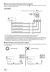
... Connecting to the Speaker Input Level System When connecting by using the Speaker-RCA Conversion Cable ( ) (sold separately), switch the Input Level and Turn-on Type Switch ( ) to this product. Front Speaker output (L)/(R) to CH1/CH2, Rear Speaker output (L)/(R) to CH3/CH4 • For the "Speaker Input Level System" setting, connecting the Remote Turn-On Lead is required if Head Unit, etc. In such a case, connect the Remote Turn-On Lead to the "REMOTE SENSING" function of this unit. One signal Proper connection Improper connection Head Unit...
... Connecting to the Speaker Input Level System When connecting by using the Speaker-RCA Conversion Cable ( ) (sold separately), switch the Input Level and Turn-on Type Switch ( ) to this product. Front Speaker output (L)/(R) to CH1/CH2, Rear Speaker output (L)/(R) to CH3/CH4 • For the "Speaker Input Level System" setting, connecting the Remote Turn-On Lead is required if Head Unit, etc. In such a case, connect the Remote Turn-On Lead to the "REMOTE SENSING" function of this unit. One signal Proper connection Improper connection Head Unit...
Owners Manual
Page 19
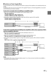
... total fuse capacity of the power and ground cables exceed 1 m, or if you connect more than one amplifier, a distribution block should be used. 17-EN length 6.5 m) S2-A55V: 4 AWG/21 mm2 (Max. Connection example when installing an amplifier alone • When the wire length from the amplifier to the vehicle's battery is (A) Wire size used for (C): 1/0 AWG/53 mm2 (or 4 AWG × 2/21 mm2 × 2) • External Fuse capacity: Make it...
... total fuse capacity of the power and ground cables exceed 1 m, or if you connect more than one amplifier, a distribution block should be used. 17-EN length 6.5 m) S2-A55V: 4 AWG/21 mm2 (Max. Connection example when installing an amplifier alone • When the wire length from the amplifier to the vehicle's battery is (A) Wire size used for (C): 1/0 AWG/53 mm2 (or 4 AWG × 2/21 mm2 × 2) • External Fuse capacity: Make it...
Owners Manual
Page 20
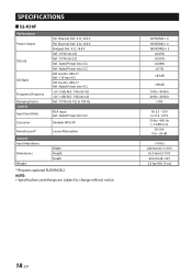
....5 mm (2-1/4") 210 mm (8-1/4") 2.2 kg (4 lb 13 oz) 18-EN SPECIFICATIONS S2-A36F Performance Power Output THD+N S/N Ratio Frequency Response Damping Factor Control Input Sensitivity Crossover Per Channel, Ref.: 4 Ω, 14.4 V Per Channel, Ref.: 2 Ω, 14.4 V Bridged, Ref.: 4 Ω, 14.4 V Ref.: 10 W into 4 Ω Ref.: 10 W into 2 Ω Ref.: Rated Power into 4 Ω Ref.: Rated Power into 2 Ω IHF A-wtd + AES-17 Ref.: 1 W into 4 Ω...
....5 mm (2-1/4") 210 mm (8-1/4") 2.2 kg (4 lb 13 oz) 18-EN SPECIFICATIONS S2-A36F Performance Power Output THD+N S/N Ratio Frequency Response Damping Factor Control Input Sensitivity Crossover Per Channel, Ref.: 4 Ω, 14.4 V Per Channel, Ref.: 2 Ω, 14.4 V Bridged, Ref.: 4 Ω, 14.4 V Ref.: 10 W into 4 Ω Ref.: 10 W into 2 Ω Ref.: Rated Power into 4 Ω Ref.: Rated Power into 2 Ω IHF A-wtd + AES-17 Ref.: 1 W into 4 Ω...

Owners Manual
Page 21
.... 19-EN NOTE: • Specifications and design are subject to −20 dB >10 kΩ 302 mm (11-7/8") 56.5 mm (2-1/4") 210 mm (8-1/4") 3.2 kg (7 lb) * Requires optional RUX-KNOB.2. S2-A55V Performance Power Output THD+N S/N Ratio Frequency Response Damping Factor Control Input Select Input Sensitivity Crossover Remote Level* General Input Impedance Dimensions Weight Per Channel, Ref.: 4 Ω, 14.4 V Per Channel, Ref.: 2 Ω, 14.4 V Bridged, Ref.: 4 Ω, 14...
.... 19-EN NOTE: • Specifications and design are subject to −20 dB >10 kΩ 302 mm (11-7/8") 56.5 mm (2-1/4") 210 mm (8-1/4") 3.2 kg (7 lb) * Requires optional RUX-KNOB.2. S2-A55V Performance Power Output THD+N S/N Ratio Frequency Response Damping Factor Control Input Select Input Sensitivity Crossover Remote Level* General Input Impedance Dimensions Weight Per Channel, Ref.: 4 Ω, 14.4 V Per Channel, Ref.: 2 Ω, 14.4 V Bridged, Ref.: 4 Ω, 14...


