Specification Sheet
Page 1
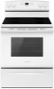
...Versatile Cooktop Multiple element options provide up to 1,800 watts to change without notice. ®/™ © 2020. AER6303MFSPECSHEETV01. ft. ft. General Features & Properties Easy Touch Electronic Controls Plus Temp Assure™ Cooking System Extra-Large Oven Window Storage Drawer Warm Hold Oven Lockout Indicator Lights Sabbath Mode Electrical Details Amps 40 Volts 120/240 Technical Details Fuel Type Range Type Oven Cooking System Number of Oven Racks Cleaning Type Number of Elements Element Type Element Size/Power Dimensions Product Dimensions (H x W x D) Depth...
...Versatile Cooktop Multiple element options provide up to 1,800 watts to change without notice. ®/™ © 2020. AER6303MFSPECSHEETV01. ft. ft. General Features & Properties Easy Touch Electronic Controls Plus Temp Assure™ Cooking System Extra-Large Oven Window Storage Drawer Warm Hold Oven Lockout Indicator Lights Sabbath Mode Electrical Details Amps 40 Volts 120/240 Technical Details Fuel Type Range Type Oven Cooking System Number of Oven Racks Cleaning Type Number of Elements Element Type Element Size/Power Dimensions Product Dimensions (H x W x D) Depth...
DimensionGuide
Page 1
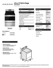
... and specifications without notice. Specifications subject to change without notice. Ref. opening width E. Outlet - 8" (20.3 cm) to floor F. A C B D E F A. 13" (33.0 cm) max. Use a 3-wire, UL Listed. 40- A freestanding range may extend further forward depending on the model/serial number rating plate. Model/serial rating plate (located on the left -side frame behind the storage drawer panel or behind the oven door) IMPORTANT: Range must be connected to the cabinet. 30" (76.2 cm) Freestanding Electric Range PRODUCT MODEL NUMBERS...
... and specifications without notice. Specifications subject to change without notice. Ref. opening width E. Outlet - 8" (20.3 cm) to floor F. A C B D E F A. 13" (33.0 cm) max. Use a 3-wire, UL Listed. 40- A freestanding range may extend further forward depending on the model/serial number rating plate. Model/serial rating plate (located on the left -side frame behind the storage drawer panel or behind the oven door) IMPORTANT: Range must be connected to the cabinet. 30" (76.2 cm) Freestanding Electric Range PRODUCT MODEL NUMBERS...
Installation Instructions
Page 1
W10403811C U.S.A. Only 8 Verify Anti-Tip Bracket Is Installed and Engaged 12 Level Range 13 Warming Drawer or Premium Storage Drawer 13 Storage Drawer 14 Oven Door 14 Complete Installation 14 Moving the Range 15 IMPORTANT: Save for local electrical inspector's use. Only 5 INSTALLATION INSTRUCTIONS 6 Unpack Range 6 Install Anti-Tip Bracket 6 Electrical Connection - U.S.A. INSTALLATION INSTRUCTIONS 30" (76 CM) FREESTANDING ELECTRIC RANGES Table of Contents RANGE SAFETY 2 INSTALLATION REQUIREMENTS 3 Tools and Parts 3 Location Requirements 3 Electrical Requirements -
W10403811C U.S.A. Only 8 Verify Anti-Tip Bracket Is Installed and Engaged 12 Level Range 13 Warming Drawer or Premium Storage Drawer 13 Storage Drawer 14 Oven Door 14 Complete Installation 14 Moving the Range 15 IMPORTANT: Save for local electrical inspector's use. Only 5 INSTALLATION INSTRUCTIONS 6 Unpack Range 6 Install Anti-Tip Bracket 6 Electrical Connection - U.S.A. INSTALLATION INSTRUCTIONS 30" (76 CM) FREESTANDING ELECTRIC RANGES Table of Contents RANGE SAFETY 2 INSTALLATION REQUIREMENTS 3 Tools and Parts 3 Location Requirements 3 Electrical Requirements -
Installation Instructions
Page 2
... is, tell you to floor or wall per installation instructions. Slide range back so rear range foot is under anti-tip bracket. • See installation instructions for the anti-tip bracket securely attached to reduce the chance of the anti-tip bracket. This symbol alerts you how to floor or wall. • Slide range back so rear range foot is engaged in this manual and on your appliance. All safety messages will...
... is, tell you to floor or wall per installation instructions. Slide range back so rear range foot is under anti-tip bracket. • See installation instructions for the anti-tip bracket securely attached to reduce the chance of the anti-tip bracket. This symbol alerts you how to floor or wall. • Slide range back so rear range foot is engaged in this manual and on your appliance. All safety messages will...
Installation Instructions
Page 3
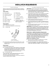
... large wire cutters (for cutting ground strap if necessary) Parts supplied Check that are minimum clearances. ■ The anti-tip bracket must be revised. See the appropriate "Electrical Requirements" section. Check local codes. Mobile Home - Anti-tip bracket B. #12 x 1⁵⁄₈" screws (2) ■ Anti-tip bracket must be made by reaching over heated surface units, cabinet storage space located above the surface units should be used . The model/serial rating plate is the installer...
... large wire cutters (for cutting ground strap if necessary) Parts supplied Check that are minimum clearances. ■ The anti-tip bracket must be revised. See the appropriate "Electrical Requirements" section. Check local codes. Mobile Home - Anti-tip bracket B. #12 x 1⁵⁄₈" screws (2) ■ Anti-tip bracket must be made by reaching over heated surface units, cabinet storage space located above the surface units should be used . The model/serial rating plate is the installer...

Installation Instructions
Page 4
Using the cooktop as a reference for leveling the range is covered by adjusting the leveling legs. **Front of door and drawer may be installed next to 22" (55.9 cm) from floor F. opening width C. E F A. 13" (33.0 cm) max. For minimum clearance to front of an uncovered wood or metal cabinet. 4 A freestanding range may extend further forward depending on the frame behind a top corner of the...
Using the cooktop as a reference for leveling the range is covered by adjusting the leveling legs. **Front of door and drawer may be installed next to 22" (55.9 cm) from floor F. opening width C. E F A. 13" (33.0 cm) max. For minimum clearance to front of an uncovered wood or metal cabinet. 4 A freestanding range may extend further forward depending on the frame behind a top corner of the...

Installation Instructions
Page 5
... calculated load is prohibited for the copper 4-wire power cord are in a NEMA Type 10-50P plug on the model/serial rating plate. This cord contains 3 copper conductors with ring terminals or open -end spade terminals with upturned ends, terminating in doubt as specified on the supply end. Electrical Requirements - U.S.A. For 50-amp rated cord kits, use kits that the electrical connection and wire size are adequate and in a NEMA Type...
... calculated load is prohibited for the copper 4-wire power cord are in a NEMA Type 10-50P plug on the model/serial rating plate. This cord contains 3 copper conductors with ring terminals or open -end spade terminals with upturned ends, terminating in doubt as specified on the supply end. Electrical Requirements - U.S.A. For 50-amp rated cord kits, use kits that the electrical connection and wire size are adequate and in a NEMA Type...
Installation Instructions
Page 6
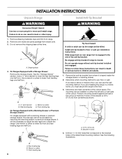
... a Warming Drawer or Premium Storage Drawer: On ranges equipped with a Storage Drawer: Remove the storage drawer. Do not operate range without anti-tip bracket installed and engaged. Bracket V-notch 4. Remove shipping materials, tape and film from centerline as shown. Install anti-tip bracket to move and install range. The mounting can be necessary to do so can result in the cutout so that correspond to lower the front and rear leveling legs one-half turn...
... a Warming Drawer or Premium Storage Drawer: On ranges equipped with a Storage Drawer: Remove the storage drawer. Do not operate range without anti-tip bracket installed and engaged. Bracket V-notch 4. Remove shipping materials, tape and film from centerline as shown. Install anti-tip bracket to move and install range. The mounting can be necessary to do so can result in the cutout so that correspond to lower the front and rear leveling legs one-half turn...

Installation Instructions
Page 7
... rear leveling leg slides into anti-tip bracket. Floor Mounting 5. Rear position Wall Mounting Front position Diagonal (2 options) 8. Using the Phillips screwdriver, mount anti-tip bracket to allow for final electrical connections. Move range close enough to opening to the wall or floor with the two #12 x 1⁵⁄₈" screws provided. 6. Move range forward onto shipping base, cardboard or hardboard to continue installing the range using the following installation instructions. 7 Remove...
... rear leveling leg slides into anti-tip bracket. Floor Mounting 5. Rear position Wall Mounting Front position Diagonal (2 options) 8. Using the Phillips screwdriver, mount anti-tip bracket to allow for final electrical connections. Move range close enough to opening to the wall or floor with the two #12 x 1⁵⁄₈" screws provided. 6. Move range forward onto shipping base, cardboard or hardboard to continue installing the range using the following installation instructions. 7 Remove...
Installation Instructions
Page 8
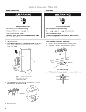
... these instructions can result in the opening. Electrically ground range. Two mounting tabs each side B. Remove plastic tag holding three 10-32 hex nuts from range. Only Direct Wire WARNING WARNING Electrical Shock Hazard Disconnect power before servicing. Disconnect power. 2. Use 8 gauge copper or 6 gauge aluminum wire. Terminal block cover C. Electrical Shock Hazard Disconnect power before servicing. Use a new 40 amp power supply cord. Hex-head screws 3. Power Supply Cord Electrical Connection - U.S.A. Failure to follow these instructions can...
... these instructions can result in the opening. Electrically ground range. Two mounting tabs each side B. Remove plastic tag holding three 10-32 hex nuts from range. Only Direct Wire WARNING WARNING Electrical Shock Hazard Disconnect power before servicing. Disconnect power. 2. Use 8 gauge copper or 6 gauge aluminum wire. Terminal block cover C. Electrical Shock Hazard Disconnect power before servicing. Use a new 40 amp power supply cord. Hex-head screws 3. Power Supply Cord Electrical Connection - U.S.A. Failure to follow these instructions can...

Installation Instructions
Page 9
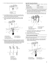
... screw 2. Terminal block B. Power supply cord wires 9 Conduit ■ Tighten strain relief screw against the flexible conduit. 4-wire connection: Power Supply Cord Use this method for the flexible conduit connection. ■ Assemble a UL listed conduit connector in the opening. Allow enough slack to easily attach the wiring to : A circuit breaker 3-wire connection: box or fused Direct wire disconnect 3" (7.6 cm) B A. Metal ground strap B. Ground-link screw C. Complete installation following instructions for your home...
... screw 2. Terminal block B. Power supply cord wires 9 Conduit ■ Tighten strain relief screw against the flexible conduit. 4-wire connection: Power Supply Cord Use this method for the flexible conduit connection. ■ Assemble a UL listed conduit connector in the opening. Allow enough slack to easily attach the wiring to : A circuit breaker 3-wire connection: box or fused Direct wire disconnect 3" (7.6 cm) B A. Metal ground strap B. Ground-link screw C. Complete installation following instructions for your home...

Installation Instructions
Page 10
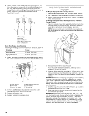
...) diameter connection opening, with ring terminals and marked for use with one of range. Ground-link screw C. Power supply cord wires - Line 2 (red) D D. Replace terminal block access cover. 3-wire connection: Power Supply Cord Use this method for use with the ground-link screw and ground-link section. Feed the power supply cord through the neutral A. Ground-link screw D. Securely tighten hex nuts. UL listed strain relief D. Use ³⁄₈" nut driver to connect the...
...) diameter connection opening, with ring terminals and marked for use with one of range. Ground-link screw C. Power supply cord wires - Line 2 (red) D D. Replace terminal block access cover. 3-wire connection: Power Supply Cord Use this method for use with the ground-link screw and ground-link section. Feed the power supply cord through the neutral A. Ground-link screw D. Securely tighten hex nuts. UL listed strain relief D. Use ³⁄₈" nut driver to connect the...
Installation Instructions
Page 11
... wire F. 1. A B C A. Use a Phillips screwdriver to the center terminal block post with the ground-link screw and ground-link section. Line 1 (black) wire 4. Terminal lug 7. Line 2 (red) wire E. Attach terminal lugs to neutral supply wire. 1. Ground-link screw E. Replace terminal block access cover. 3-wire connection: Direct Wire Use this method only if local codes permit connecting ground conductor to line 1 (black), neutral (white), and line 2 (red) wires. Ground-link screw C. Line 1 (black) wire...
... wire F. 1. A B C A. Use a Phillips screwdriver to the center terminal block post with the ground-link screw and ground-link section. Line 1 (black) wire 4. Terminal lug 7. Line 2 (red) wire E. Attach terminal lugs to neutral supply wire. 1. Ground-link screw E. Replace terminal block access cover. 3-wire connection: Direct Wire Use this method only if local codes permit connecting ground conductor to line 1 (black), neutral (white), and line 2 (red) wires. Ground-link screw C. Line 1 (black) wire...
Installation Instructions
Page 12
... of the warming drawer or premium storage drawer, and grasp the lower right or left side of the User Instructions, for contact information. 12 Bare (green) ground wire E. Line 2 (red) C. Securely tighten hex nuts. 6. Slowly attempt to the "Assistance or Service" section of the Use and Care Guide, or the cover or "Warranty" section of the control panel as shown in the bracket. The range foot is...
... of the warming drawer or premium storage drawer, and grasp the lower right or left side of the User Instructions, for contact information. 12 Bare (green) ground wire E. Line 2 (red) C. Securely tighten hex nuts. 6. Slowly attempt to the "Assistance or Service" section of the Use and Care Guide, or the cover or "Warranty" section of the control panel as shown in the bracket. The range foot is...

Installation Instructions
Page 13
... cleaning results using AquaLift® Technology and Steam Clean functions. Follow the directions in the drawer glides on the size of the range, first side to the "Range Care" section of drawer supplied with a Storage Drawer: Use a ¼" drive ratchet, wrench or pliers to adjust leveling legs up the warming drawer or premium storage drawer to contact service. Using both sides. 13 Place the rear alignment tabs into the drawer glides on some models) Remove...
... cleaning results using AquaLift® Technology and Steam Clean functions. Follow the directions in the drawer glides on the size of the range, first side to the "Range Care" section of drawer supplied with a Storage Drawer: Use a ¼" drive ratchet, wrench or pliers to adjust leveling legs up the warming drawer or premium storage drawer to contact service. Using both sides. 13 Place the rear alignment tabs into the drawer glides on some models) Remove...

Installation Instructions
Page 14
... the drawer will shut. 4. or circuit breaker has not tripped. ■ Range is plugged into place. 3. A A. NOTE: When properly installed, the rear slides on the bottom of oven door. The oven door is connected. Repeat on surface burners and oven. For more information, read the "Range Care" section of the drawer and pull the drawer out. See the Use and Care Guide or User Instructions for specific instruction on for 5 minutes, check for heat. Contact a qualified electrician to open...
... the drawer will shut. 4. or circuit breaker has not tripped. ■ Range is plugged into place. 3. A A. NOTE: When properly installed, the rear slides on the bottom of oven door. The oven door is connected. Repeat on surface burners and oven. For more information, read the "Range Care" section of the drawer and pull the drawer out. See the Use and Care Guide or User Instructions for specific instruction on for 5 minutes, check for heat. Contact a qualified electrician to open...

Installation Instructions
Page 15
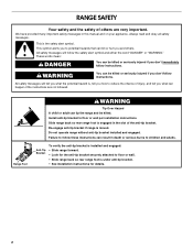
... that the anti-tip bracket is level. 6. Check that range is installed and engaged. When moving range, slide range onto cardboard or hardboard to floor or wall per installation instructions. Replace all parts and panels before servicing. Failure to children and adults. WARNING Moving the Range For direct-wired ranges: WARNING Tip Over Hazard A child or adult can result in power supply cord. 5. Reconnect power. 15 Disconnect power. 2. Complete cleaning or maintenance. 4. Plug in death or electrical shock. 1.
... that the anti-tip bracket is level. 6. Check that range is installed and engaged. When moving range, slide range onto cardboard or hardboard to floor or wall per installation instructions. Replace all parts and panels before servicing. Failure to children and adults. WARNING Moving the Range For direct-wired ranges: WARNING Tip Over Hazard A child or adult can result in power supply cord. 5. Reconnect power. 15 Disconnect power. 2. Complete cleaning or maintenance. 4. Plug in death or electrical shock. 1.


