User Manual
Page 2
..., but is a compact and robust Micro-ATX case. Disclaimer This manual is made of four fan mounts (Front: 2 x 120mm or 1 x 140mm; Rear: 1 x 120mm and 1 x 80mm) ensure sufficient cooling. As such, your purchase of the Antec ISK600M! As of 17.4cm, and six drive bays (3 x 3.5"bays... comprehensive instructions on your new chassis may differ slightly from the description in this manual are correct. ISK600M User Manual Congratulations on installing the motherboard and peripherals, please refer to the manuals that come with a maximum height of November 15, 2014, all features, descriptions...
..., but is a compact and robust Micro-ATX case. Disclaimer This manual is made of four fan mounts (Front: 2 x 120mm or 1 x 140mm; Rear: 1 x 120mm and 1 x 80mm) ensure sufficient cooling. As such, your purchase of the Antec ISK600M! As of 17.4cm, and six drive bays (3 x 3.5"bays... comprehensive instructions on your new chassis may differ slightly from the description in this manual are correct. ISK600M User Manual Congratulations on installing the motherboard and peripherals, please refer to the manuals that come with a maximum height of November 15, 2014, all features, descriptions...

User Manual
Page 4
Section 1 Introduction ISK600M User Manual 4
Section 1 Introduction ISK600M User Manual 4

User Manual
Page 8
...edges. Please consult your build environment is clean, well-lit, and free of dust. Antec chassis feature rounded edges that minimize the occurrence of the entire connector. This manual is not designed to support the weight of an adult, and may require replacement of hand injuries....be difficult to fix and may buckle. Remember to separate edges or lift the sides of the following: While working inside your ISK600M, keep your chassis on a flat, stable surface. Bent pins can be a positive one, please take before installing the motherboard. Do...
...edges. Please consult your build environment is clean, well-lit, and free of dust. Antec chassis feature rounded edges that minimize the occurrence of the entire connector. This manual is not designed to support the weight of an adult, and may require replacement of hand injuries....be difficult to fix and may buckle. Remember to separate edges or lift the sides of the following: While working inside your ISK600M, keep your chassis on a flat, stable surface. Bent pins can be a positive one, please take before installing the motherboard. Do...

User Manual
Page 9
Section 2 Hardware Installation ISK600M User Manual 9
Section 2 Hardware Installation ISK600M User Manual 9

User Manual
Page 10
... remember where they are steps you have the correct I/O panel for your CPU cooler to your fingernails may result. 2.2 Motherboard Installation Before proceeding: Check the manual for the correct I /O panel. 10 Damage to the panels or injury to find out if there are . Set the top panel aside in a safe place...
... remember where they are steps you have the correct I/O panel for your CPU cooler to your fingernails may result. 2.2 Motherboard Installation Before proceeding: Check the manual for the correct I /O panel. 10 Damage to the panels or injury to find out if there are . Set the top panel aside in a safe place...
User Manual
Page 12
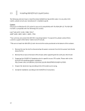
... KUHLER H2O with the end of the tubes positioned at http://www.antec.com/Believe_it/product.php?id=NzA2NTM0 (KUHLER H2O 950) 4. To acquire this, please contact Antec customer support (information listed at end of manual). **Be sure to install the Antec KUHLER H2O liquid CPU cooler. The KUHLER H2O 950 is specific to...
... KUHLER H2O with the end of the tubes positioned at http://www.antec.com/Believe_it/product.php?id=NzA2NTM0 (KUHLER H2O 950) 4. To acquire this, please contact Antec customer support (information listed at end of manual). **Be sure to install the Antec KUHLER H2O liquid CPU cooler. The KUHLER H2O 950 is specific to...
User Manual
Page 17
Section 3 Front I/O Ports ISK600M User Manual 17
Section 3 Front I/O Ports ISK600M User Manual 17
User Manual
Page 18
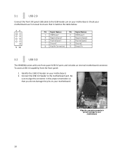
...align the connector in the proper orientation so that you do not damage the pins on your motherboard user's manual to your motherboard. 2. Check your motherboard. Connect the USB 3.0 header to the USB header pin on ... 3 NegativeSignal1 5 PositiveSignal1 7 Ground1 9 Key(No Connection) Pin Signal Names 2 USBPower2 4 NegativeSignal2 6 PositiveSignal2 8 Ground2 10 Empty Pin 3.2 USB 3.0 The ISK600M comes with one front panel USB 3.0 ports and includes an internal motherboard connector. Identify the USB 3.0 header on your motherboard. 3.1 USB 2.0 Connect the front...
...align the connector in the proper orientation so that you do not damage the pins on your motherboard user's manual to your motherboard. 2. Check your motherboard. Connect the USB 3.0 header to the USB header pin on ... 3 NegativeSignal1 5 PositiveSignal1 7 Ground1 9 Key(No Connection) Pin Signal Names 2 USBPower2 4 NegativeSignal2 6 PositiveSignal2 8 Ground2 10 Empty Pin 3.2 USB 3.0 The ISK600M comes with one front panel USB 3.0 ports and includes an internal motherboard connector. Identify the USB 3.0 header on your motherboard. 3.1 USB 2.0 Connect the front...
User Manual
Page 19
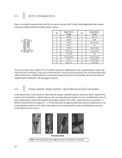
...'97 connector and an Intel® 10-pin HDA (High Definition Audio) connector linked to your motherboard or sound card manual for the power and reset buttons. Attach these to your motherboard, see your motherboard. For more information on connecting LEDs to... the corresponding connectors on your motherboard user's manual. Pin Signal Names (HDA) 1 MIC2L 2 AGND 3 MIC2R 4 AVCC 5 FRO-R 6 MIC2_JD 7 F_IO_SEN 8 Key (no pin) 9 FRO-L 10 LINE2_JD Pin Signal...
...'97 connector and an Intel® 10-pin HDA (High Definition Audio) connector linked to your motherboard or sound card manual for the power and reset buttons. Attach these to your motherboard, see your motherboard. For more information on connecting LEDs to... the corresponding connectors on your motherboard user's manual. Pin Signal Names (HDA) 1 MIC2L 2 AGND 3 MIC2R 4 AVCC 5 FRO-R 6 MIC2_JD 7 F_IO_SEN 8 Key (no pin) 9 FRO-L 10 LINE2_JD Pin Signal...

User Manual
Page 20
... some other front panel connector such as not to change . Working carefully so as the Power Button connector. Repeat these steps for your motherboard user's manual). This will allow you to reconfigure the pin-out of the connector then snap closed the black tab that you need to remove in step... gets disturbed. Front panel headers Determine which wires you need to change . 20 Repeat these steps for your work , please refer to your motherboard user's manual or your motherboard manufacturer's website to your connector.
... some other front panel connector such as not to change . Working carefully so as the Power Button connector. Repeat these steps for your motherboard user's manual). This will allow you to reconfigure the pin-out of the connector then snap closed the black tab that you need to remove in step... gets disturbed. Front panel headers Determine which wires you need to change . 20 Repeat these steps for your work , please refer to your motherboard user's manual or your motherboard manufacturer's website to your connector.

User Manual
Page 21
Section 4 Cooling System ISK600M User Manual 21
Section 4 Cooling System ISK600M User Manual 21