Manual
Page 2
... this manual are correct. P100 User Manual Congratulations on installing the motherboard and peripherals, please refer to the manuals that minimize system noise. Disclaimer This manual is intended only as a guide for the optimal building experience. At Antec, we continually refine and improve our products to 7 expansion slots, the P100 also supports 2 tool-less 5.25" drives and 7 tool-less 3.5"/ 2.5" drives. It features Antec's award...
... this manual are correct. P100 User Manual Congratulations on installing the motherboard and peripherals, please refer to the manuals that minimize system noise. Disclaimer This manual is intended only as a guide for the optimal building experience. At Antec, we continually refine and improve our products to 7 expansion slots, the P100 also supports 2 tool-less 5.25" drives and 7 tool-less 3.5"/ 2.5" drives. It features Antec's award...
Manual
Page 3
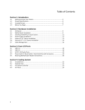
... 2: Hardware Installation 2.1 Setting Up ...9 2.2 Motherboard Installation 9 2.3 Installing KUHLER H2O Liquid Coolers 11 2.4 Power Supply Installation 12 2.5 External 5.25" Device Installation 13 2.6 Internal 3.5" / 2.5" Device Installation 14 2.7 Cable Management 16 Section 3: Front I/O Ports 3.1 USB 2.0...18 3.2 USB 3.0...18 3.3 AC'97 / HD Audio Ports 19 3.4 Power Switch / Reset Switch / Hard Disk Drive LED Connectors 19 3.5 Rewiring Motherboard Header Connections 20 Section 4: Cooling System 4.1 Included Fans ...22 4.2 Optional Fans ...22 4.3 Fan Switch Controller 23 4.4 Air...
... 2: Hardware Installation 2.1 Setting Up ...9 2.2 Motherboard Installation 9 2.3 Installing KUHLER H2O Liquid Coolers 11 2.4 Power Supply Installation 12 2.5 External 5.25" Device Installation 13 2.6 Internal 3.5" / 2.5" Device Installation 14 2.7 Cable Management 16 Section 3: Front I/O Ports 3.1 USB 2.0...18 3.2 USB 3.0...18 3.3 AC'97 / HD Audio Ports 19 3.4 Power Switch / Reset Switch / Hard Disk Drive LED Connectors 19 3.5 Rewiring Motherboard Header Connections 20 Section 4: Cooling System 4.1 Included Fans ...22 4.2 Optional Fans ...22 4.3 Fan Switch Controller 23 4.4 Air...
Manual
Page 5
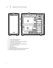
CPU cutout 8. Motherboard mount: ATX, Micro ATX or Mini-ITX 10. Cable routing holes 9. 1.1 Getting to Know Your Chassis 1. 2 x 5.25" tool-less drive bays 2. 7 x 3.5" / 2.5" drive trays 3. 2 x 120 /140 mm top exhaust fans (optional) 4. 1 x 120 mm rear exhaust fan 5. 2 x 120 /140 mm front intake fans (optional) 6. 7 x PCI-E expansion slots 7. Front Ports (USB 3.0, USB 2.0, Audio I/O) 5
CPU cutout 8. Motherboard mount: ATX, Micro ATX or Mini-ITX 10. Cable routing holes 9. 1.1 Getting to Know Your Chassis 1. 2 x 5.25" tool-less drive bays 2. 7 x 3.5" / 2.5" drive trays 3. 2 x 120 /140 mm top exhaust fans (optional) 4. 1 x 120 mm rear exhaust fan 5. 2 x 120 /140 mm front intake fans (optional) 6. 7 x PCI-E expansion slots 7. Front Ports (USB 3.0, USB 2.0, Audio I/O) 5

Manual
Page 6
Motherboard screw (10) E. p. p. Front fan screw (4) B. HDD screw (30) C. Motherboard standoff(10) F. m, 18dB(A) - 1 x 120 mm Rear FDB fan, 1200 r. Audio In/Out 1.3 Included Screws An inventory of all screws and intended usage and quantity is provided here: A. 1.2 Chassis Specifications Chassis Type Chassis Color Dimensions Weight Cooling Drive Bays Expansion Slots Motherboard Size Front I/O Panel Mid-Tower Black with aluminum...
Motherboard screw (10) E. p. p. Front fan screw (4) B. HDD screw (30) C. Motherboard standoff(10) F. m, 18dB(A) - 1 x 120 mm Rear FDB fan, 1200 r. Audio In/Out 1.3 Included Screws An inventory of all screws and intended usage and quantity is provided here: A. 1.2 Chassis Specifications Chassis Type Chassis Color Dimensions Weight Cooling Drive Bays Expansion Slots Motherboard Size Front I/O Panel Mid-Tower Black with aluminum...

Manual
Page 7
...; Remember to use the right tools for specific mounting instructions and troubleshooting. Nonetheless, exercise caution and control when handling chassis interiors. Make sure your build environment is not designed to support the weight of the entire connector. This manual is not designed to cover CPU, RAM, or expansion card installation. Do not touch the unshielded components or...
...; Remember to use the right tools for specific mounting instructions and troubleshooting. Nonetheless, exercise caution and control when handling chassis interiors. Make sure your build environment is not designed to support the weight of the entire connector. This manual is not designed to cover CPU, RAM, or expansion card installation. Do not touch the unshielded components or...

Manual
Page 8
Section 2 Hardware Installation P100 User Manual 8
Section 2 Hardware Installation P100 User Manual 8

Manual
Page 9
... to the panels or injury to your fingernails may result. 2.2 Motherboard Installation Before proceeding: Check the manual for your CPU cooler to pry or lift the panels. Remove the panel by gripping the end of the chassis. CAUTION: Do not use your motherboard. Make sure you...the panel thumbscrews aside carefully and remember where they are steps you have the correct I /O panel. 2.1 Setting Up Put the case upright on a flat, stable surface so that the rear panel (power supply and expansion slots) is facing you have the correct I/O panel for the correct I /O panel. 9...
... to the panels or injury to your fingernails may result. 2.2 Motherboard Installation Before proceeding: Check the manual for your CPU cooler to pry or lift the panels. Remove the panel by gripping the end of the chassis. CAUTION: Do not use your motherboard. Make sure you...the panel thumbscrews aside carefully and remember where they are steps you have the correct I /O panel. 2.1 Setting Up Put the case upright on a flat, stable surface so that the rear panel (power supply and expansion slots) is facing you have the correct I/O panel for the correct I /O panel. 9...

Manual
Page 10
These are lined up 2. They may electrify your chassis exterior if left connected. 3. CAUTION Make sure to accommodate other form factors. 1. Use the provided motherboard mounting screws to secure your motherboard into the standoffs. 10 Align the ...Standard ATX motherboards but can be relocated to remove any unused motherboard standoffs. Screw your motherboard into the standoffs with six preinstalled motherboard standoffs. The P100 comes with the provided motherboard mounting screws. Install the motherboard standoffs by aligning the motherboard with the standoff holes...
These are lined up 2. They may electrify your chassis exterior if left connected. 3. CAUTION Make sure to accommodate other form factors. 1. Use the provided motherboard mounting screws to secure your motherboard into the standoffs. 10 Align the ...Standard ATX motherboards but can be relocated to remove any unused motherboard standoffs. Screw your motherboard into the standoffs with six preinstalled motherboard standoffs. The P100 comes with the provided motherboard mounting screws. Install the motherboard standoffs by aligning the motherboard with the standoff holes...

Manual
Page 11
... specific to the KUHLER H2O installation guide, available at the bottom of the radiator. 1. To acquire this, please contact Antec customer support (information listed at end of manual). **Be sure to install the KUHLER H2O with the end of the chassis while supporting the fan with your other CPU coolers, please consult your motherboard's CPU socket to ensure its compatibility with the following instructs...
... specific to the KUHLER H2O installation guide, available at the bottom of the radiator. 1. To acquire this, please contact Antec customer support (information listed at end of manual). **Be sure to install the KUHLER H2O with the end of the chassis while supporting the fan with your other CPU coolers, please consult your motherboard's CPU socket to ensure its compatibility with the following instructs...
Manual
Page 12
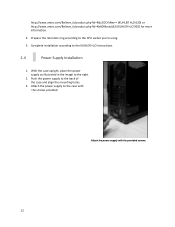
... the mounting holes. 3. Attach the power supply with the screws provided. Attach the power supply to the case with the provided screws. 12 Push the power supply to the right. 2. Complete installation according to the CPU socket you're using. 5. Prepare the retention ring according to the KUHLER H2O instructions. 2.4 Power Supply Installation 1. http://www.antec.com/Believe_it/product.php?id=Mjc2OCYxNw...
... the mounting holes. 3. Attach the power supply with the screws provided. Attach the power supply to the case with the provided screws. 12 Push the power supply to the right. 2. Complete installation according to the CPU socket you're using. 5. Prepare the retention ring according to the KUHLER H2O instructions. 2.4 Power Supply Installation 1. http://www.antec.com/Believe_it/product.php?id=Mjc2OCYxNw...
Manual
Page 13
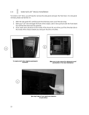
.... Slide your drive, pull the drive bay tab on the inside of the chassis toward you will feel the drive lock into position. 3. With the side panel off, carefully push the drive bay cover out of the chassis until it lines up flush with the front bezel. 2.5 External 5.25" Device Installation To install a 5.25" drive, you and...
.... Slide your drive, pull the drive bay tab on the inside of the chassis toward you will feel the drive lock into position. 3. With the side panel off, carefully push the drive bay cover out of the chassis until it lines up flush with the front bezel. 2.5 External 5.25" Device Installation To install a 5.25" drive, you and...
Manual
Page 14
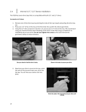
... Section 1.3), secure your drive. You will minimize the grommets' ability to find the drive's holes. 4. Remove one of the drive trays by pinching the ends of the drive's holes then using your hand to reduce vibration. Use your device click into the bay. 2.6 Internal 3.5" / 2.5" Device Installation The P100 has seven drive bays that are compatible with the silicone grommets...
... Section 1.3), secure your drive. You will minimize the grommets' ability to find the drive's holes. 4. Remove one of the drive trays by pinching the ends of the drive's holes then using your hand to reduce vibration. Use your device click into the bay. 2.6 Internal 3.5" / 2.5" Device Installation The P100 has seven drive bays that are compatible with the silicone grommets...
Manual
Page 15
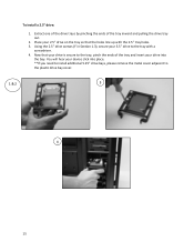
... the tray inward and pulling the drive tray out. 2. To install a 2.5" drive: 1. Extract one of the drive trays by pinching the ends of the tray and insert your 2.5" drive on the tray so that the holes line up with a screwdriver. 4. Place your drive into place. **If you need to install additional 5.25" drive bays, please remove the metal cover...
... the tray inward and pulling the drive tray out. 2. To install a 2.5" drive: 1. Extract one of the drive trays by pinching the ends of the tray and insert your 2.5" drive on the tray so that the holes line up with a screwdriver. 4. Place your drive into place. **If you need to install additional 5.25" drive bays, please remove the metal cover...

Manual
Page 17
Section 3 Front I/O Ports P100 User Manual 17
Section 3 Front I/O Ports P100 User Manual 17
Manual
Page 18
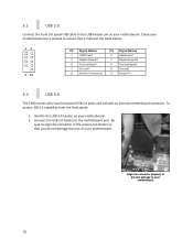
... on your motherboard. 3.1 USB 2.0 Connect the front I/O panel USB cable to the USB header pin on your motherboard. 2. Align the connector properly to prevent damage to the motherboard port. Be sure to ensure that you do not damage the pins on your motherboard. Connect the USB 3.0 header to your motherboard user's manual to align the connector...
... on your motherboard. 3.1 USB 2.0 Connect the front I/O panel USB cable to the USB header pin on your motherboard. 2. Align the connector properly to prevent damage to the motherboard port. Be sure to ensure that you do not damage the pins on your motherboard. Connect the USB 3.0 header to your motherboard user's manual to align the connector...
Manual
Page 19
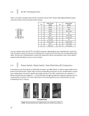
... reset buttons. Even if your system supports both standards, only use one connector. 3.4 Power Switch / Reset Switch / Hard Disk Drive LED Connectors Connected to the front panel of the chassis. For more information on connecting LEDs to the corresponding connectors on your motherboard. White or black wires are positive ( + ). Attach these to your motherboard, see your motherboard user's manual. If the LED does not light...
... reset buttons. Even if your system supports both standards, only use one connector. 3.4 Power Switch / Reset Switch / Hard Disk Drive LED Connectors Connected to the front panel of the chassis. For more information on connecting LEDs to the corresponding connectors on your motherboard. White or black wires are positive ( + ). Attach these to your motherboard, see your motherboard user's manual. If the LED does not light...

Manual
Page 22
... intake 120 mm fans You can install these fans using 2 of the long screws provided (A in the top-left and lower-right holes first. 22 Align the fan with two standard top 120 mm TwoCool™ fans and a standard rear 120 mm TwoCool™ fan. The default fan speed setting is Low. 120 mm TwoCool™ fan specifications: Size 120 x...84 m³/ min (30.1CFM) Static Pressure 1.21 mm-H2O (0.05 inch-H2O) 0.49 mm-H2O (0.02i nch-H2O) Noise 27.9 dBA 16.9 dBA Input Power 3.6W 2.2W 4.2 Optional Fans The P100 includes mounts for up to screw in the fan in Section 1.3). Be sure to four more...
... intake 120 mm fans You can install these fans using 2 of the long screws provided (A in the top-left and lower-right holes first. 22 Align the fan with two standard top 120 mm TwoCool™ fans and a standard rear 120 mm TwoCool™ fan. The default fan speed setting is Low. 120 mm TwoCool™ fan specifications: Size 120 x...84 m³/ min (30.1CFM) Static Pressure 1.21 mm-H2O (0.05 inch-H2O) 0.49 mm-H2O (0.02i nch-H2O) Noise 27.9 dBA 16.9 dBA Input Power 3.6W 2.2W 4.2 Optional Fans The P100 includes mounts for up to screw in the fan in Section 1.3). Be sure to four more...

Manual
Page 24
... likely have to wash the installed air filter. Remove the filter by pushing down on environmental conditions. Open the front door by pulling on system usage (users whose systems run 24/7 will... 24 Not washing the air filter will result in the P100 that can be unlocked for maintenance and locked for transport. The P100 features a removable PSU filter that can be removed and washed... To remove the PSU filter, push the ends of the chassis. 4.4 Air Filters There are two filters in higher system temperatures and possible stability problems. We recommend checking the air filter at ...
... likely have to wash the installed air filter. Remove the filter by pushing down on environmental conditions. Open the front door by pulling on system usage (users whose systems run 24/7 will... 24 Not washing the air filter will result in the P100 that can be unlocked for maintenance and locked for transport. The P100 features a removable PSU filter that can be removed and washed... To remove the PSU filter, push the ends of the chassis. 4.4 Air Filters There are two filters in higher system temperatures and possible stability problems. We recommend checking the air filter at ...

Manual
Page 25
Antec, Inc. 47900 Fremont Blvd. Reproduction in whole or in part without written permission is prohibited. 25 All rights reserved. Stuttgartstraat 12 3047 AS Rotterdam The Netherlands tel: +49-40-226139-22 fax: +31 (0) 10 437-1752 Technical Support US &Canada 1-800-22ANTEC customersupport@antec.com Europe +31 (0) 10 462-2060 europe.techsupport@antec.com www.antec.com © Copyright 2011 Antec, Inc. Fremont, CA94538 tel: 510-770-1200 fax: 510-770-1288 Antec Europe B.V. All trademarks are the property of their respective owners.
Antec, Inc. 47900 Fremont Blvd. Reproduction in whole or in part without written permission is prohibited. 25 All rights reserved. Stuttgartstraat 12 3047 AS Rotterdam The Netherlands tel: +49-40-226139-22 fax: +31 (0) 10 437-1752 Technical Support US &Canada 1-800-22ANTEC customersupport@antec.com Europe +31 (0) 10 462-2060 europe.techsupport@antec.com www.antec.com © Copyright 2011 Antec, Inc. Fremont, CA94538 tel: 510-770-1200 fax: 510-770-1288 Antec Europe B.V. All trademarks are the property of their respective owners.
Product Flyer
Page 1
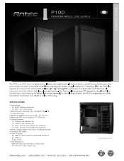
...) RoHS svo" With a great price to feature ratio the P100 is engineered with Quiet Computing' Technology, and stands in a class of its own. As with internal motherboard connector - 2 x USB 2.0 - Audio In/Out • Unit Dimensions: - 484 mm (H) x 220 mm (W) x 523 mm (D) - 19" (H) x 8.7" (W) x 20.6" (D) • I /O ports: - 2 x USB 3.0 with all Antec chassis' the P100 is the only economical...
...) RoHS svo" With a great price to feature ratio the P100 is engineered with Quiet Computing' Technology, and stands in a class of its own. As with internal motherboard connector - 2 x USB 2.0 - Audio In/Out • Unit Dimensions: - 484 mm (H) x 220 mm (W) x 523 mm (D) - 19" (H) x 8.7" (W) x 20.6" (D) • I /O ports: - 2 x USB 3.0 with all Antec chassis' the P100 is the only economical...

