
Manual
Page 1
...) / + 866-(0)800-060-696 (AP) Like all models in /out jacks. The P380 is almost inaudible even when the fans are spinning at front - 1 x 360mm radiator /1 x 240mm radiator on the top • Front I/O Ports - 2 x USB3.0; 2 x USB2.0; SPECIFICATIONS: • Case Type: Full-Tower • 8 Drive bays: - 1 x Slim optical drive bay - 8 x 3.5"/2.5" tool-less HDD bays • Motherboards: SSI CEB, E-ATX, ATX...
...) / + 866-(0)800-060-696 (AP) Like all models in /out jacks. The P380 is almost inaudible even when the fans are spinning at front - 1 x 360mm radiator /1 x 240mm radiator on the top • Front I/O Ports - 2 x USB3.0; 2 x USB2.0; SPECIFICATIONS: • Case Type: Full-Tower • 8 Drive bays: - 1 x Slim optical drive bay - 8 x 3.5"/2.5" tool-less HDD bays • Motherboards: SSI CEB, E-ATX, ATX...

User Manual
Page 2
... fans are correct. The P380 does not include a power supply. P380 User Manual Congratulations on installing the motherboard and peripherals, please refer to the manuals that come with those components. 2 The P380 also offers advanced computing features like dual power / reset button design, grommet-lined cable routing paths, elegant aluminum front panel features two well-placed USB 3.0 and USB 2.0 ports, and audio in this manual...
... fans are correct. The P380 does not include a power supply. P380 User Manual Congratulations on installing the motherboard and peripherals, please refer to the manuals that come with those components. 2 The P380 also offers advanced computing features like dual power / reset button design, grommet-lined cable routing paths, elegant aluminum front panel features two well-placed USB 3.0 and USB 2.0 ports, and audio in this manual...
User Manual
Page 3
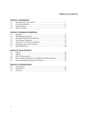
... Begin 7 Section 2: Hardware Installation 2.1 Setting Up...9 2.2 Motherboard Installation 10 2.3 Installing KUHLER H2O Liquid Coolers 11 2.4 Power Supply Installation 12 2.5 Internal 3.5" / 2.5" Device Installation 13 2.6 Slim Optical Drive Tray Installation 17 2.7 Cable Management 18 Section 3: Front I/O Ports 3.1 USB 2.0 ...20 3.2 USB 3.0 ...20 3.3 AC'97 / HD Audio Ports 21 3.4 Power Switch / Reset Switch / Hard Disk Drive LED Connectors 22 3.5 Rewiring Motherboard Header Connections 22 Section 4: Cooling System 4.1 Included Fans 25 4.2 Optional Fans 26 4.3 Air Filters ...27...
... Begin 7 Section 2: Hardware Installation 2.1 Setting Up...9 2.2 Motherboard Installation 10 2.3 Installing KUHLER H2O Liquid Coolers 11 2.4 Power Supply Installation 12 2.5 Internal 3.5" / 2.5" Device Installation 13 2.6 Slim Optical Drive Tray Installation 17 2.7 Cable Management 18 Section 3: Front I/O Ports 3.1 USB 2.0 ...20 3.2 USB 3.0 ...20 3.3 AC'97 / HD Audio Ports 21 3.4 Power Switch / Reset Switch / Hard Disk Drive LED Connectors 22 3.5 Rewiring Motherboard Header Connections 22 Section 4: Cooling System 4.1 Included Fans 25 4.2 Optional Fans 26 4.3 Air Filters ...27...
User Manual
Page 5
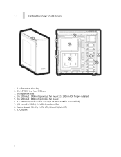
Audio In/Out 8. Motherboards: SSI CEB, E-ATX, ATX, Micro ATX, Mini-ITX 9. 1.1 Getting to Know Your Chassis 1. 1 x slim optical drive bay 2. 8 x 3.5"/2.5" tool-less HDD bays 3. 9 x Expansion Slots 4. 3 x 120mm/2 x 140mm top exhaust fan mount (2 x 140mm FDB fan pre-installed) 5. 3 x 120mm/2 x 140mm front intake fan mount 6. 1 x 120 mm rear exhaust fan mount (1 x 120mm FDB fan pre-installed) 7. CPU cutout 5 I/O Ports: 2 x USB3.0; 2 x USB2.0;
Audio In/Out 8. Motherboards: SSI CEB, E-ATX, ATX, Micro ATX, Mini-ITX 9. 1.1 Getting to Know Your Chassis 1. 1 x slim optical drive bay 2. 8 x 3.5"/2.5" tool-less HDD bays 3. 9 x Expansion Slots 4. 3 x 120mm/2 x 140mm top exhaust fan mount (2 x 140mm FDB fan pre-installed) 5. 3 x 120mm/2 x 140mm front intake fan mount 6. 1 x 120 mm rear exhaust fan mount (1 x 120mm FDB fan pre-installed) 7. CPU cutout 5 I/O Ports: 2 x USB3.0; 2 x USB2.0;

User Manual
Page 6
...-mount screw (32) F. 1.2 Chassis Specifications Chassis Type Chassis Color Dimensions Weight Cooling Drive Bays Expansion Slots Motherboard Size Front I/O Panel Full Tower Black 21.85" (H) x 8.80" (W) x 21.92" (D) 555 mm (H) x 223.6 mm (W) x 557 mm (D) 27 lbs / 12.25 kg - 3 x 120mm/2 x 140mm top exhaust fan mount(2 x 140mm FDB fan pre-installed) - 3 x 120mm/2 x 140mm front intake fan mount - 1 x 120 mm rear...
...-mount screw (32) F. 1.2 Chassis Specifications Chassis Type Chassis Color Dimensions Weight Cooling Drive Bays Expansion Slots Motherboard Size Front I/O Panel Full Tower Black 21.85" (H) x 8.80" (W) x 21.92" (D) 555 mm (H) x 223.6 mm (W) x 557 mm (D) 27 lbs / 12.25 kg - 3 x 120mm/2 x 140mm top exhaust fan mount(2 x 140mm FDB fan pre-installed) - 3 x 120mm/2 x 140mm front intake fan mount - 1 x 120 mm rear...

User Manual
Page 7
... manual for your CPU cooler to find out if there are steps you connect a cable, ensure that both connectors are correctly aligned and oriented. Nonetheless, exercise caution and control when handling chassis interiors. Do not touch the unshielded components or contacts on a flat, stable surface. Do not use the right tools for specific mounting instructions and troubleshooting...
... manual for your CPU cooler to find out if there are steps you connect a cable, ensure that both connectors are correctly aligned and oriented. Nonetheless, exercise caution and control when handling chassis interiors. Do not touch the unshielded components or contacts on a flat, stable surface. Do not use the right tools for specific mounting instructions and troubleshooting...

User Manual
Page 8
Section 2 Hardware Installation P380 User Manual 8
Section 2 Hardware Installation P380 User Manual 8
User Manual
Page 10
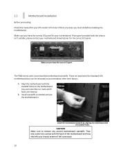
...you have the correct I/O panel. Install standoffs as needed and put the motherboard in. CAUTION Make sure to accommodate other form factors. The P380 comes with the back of the motherboard and may electrify your chassis exterior if left connected. 10 These are steps you have... the correct I /O panel. Make sure you must do before installing the motherboard. A. 2.2 Motherboard Installation Before proceeding: Check the manual for your...
...you have the correct I/O panel. Install standoffs as needed and put the motherboard in. CAUTION Make sure to accommodate other form factors. The P380 comes with the back of the motherboard and may electrify your chassis exterior if left connected. 10 These are steps you have... the correct I /O panel. Make sure you must do before installing the motherboard. A. 2.2 Motherboard Installation Before proceeding: Check the manual for your...
User Manual
Page 11
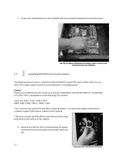
... sure to install the KUHLER H2O with the following instructs how to ensure its compatibility with the provided motherboard mounting screws. C. Remove the rear fan by first disconnecting the power connector from the fan power hub directly above the fan. 11 Disconnect the 3-pin power connector. Screw your manufacturer's installation guide. To acquire this, please contact Antec customer support (information listed at end of the...
... sure to install the KUHLER H2O with the following instructs how to ensure its compatibility with the provided motherboard mounting screws. C. Remove the rear fan by first disconnecting the power connector from the fan power hub directly above the fan. 11 Disconnect the 3-pin power connector. Screw your manufacturer's installation guide. To acquire this, please contact Antec customer support (information listed at end of the...
User Manual
Page 12
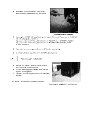
....antec.com/Believe_it/product.php?id=NzA0MzcwJjE3 (KUHLER H2O 920) for PSU filter removal instructions Attach the power supply with your CPU socket. Please refer to remove it. D. B. B. Preparing the KUHLER H2O backplate is specific to the back of the chassis while supporting the fan with the provided screws. 12 E. Push the power supply to your other hand. Complete installation...
....antec.com/Believe_it/product.php?id=NzA0MzcwJjE3 (KUHLER H2O 920) for PSU filter removal instructions Attach the power supply with your CPU socket. Please refer to remove it. D. B. B. Preparing the KUHLER H2O backplate is specific to the back of the chassis while supporting the fan with the provided screws. 12 E. Push the power supply to your other hand. Complete installation...
User Manual
Page 13
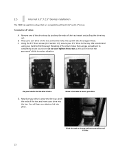
... of the tray inward and pulling the drive tray out. Use your drive into place. Now that your drive is secure to the tray, pinch the ends of the tray and insert your hand to find the drive's holes. To install a 3.5" drive: A. We recommend using a screwdriver to...as this will hear your 3.5" drive on the tray so that the holes line up with both 3.5" and 2.5" drives. You will minimize the grommets' ability to completely secure your drive. 2.5 Internal 3.5" / 2.5" Device Installation The P380 has eight drive bays that are compatible with the silicone grommets. B. ...
... of the tray inward and pulling the drive tray out. Use your drive into place. Now that your drive is secure to the tray, pinch the ends of the tray and insert your hand to find the drive's holes. To install a 3.5" drive: A. We recommend using a screwdriver to...as this will hear your 3.5" drive on the tray so that the holes line up with both 3.5" and 2.5" drives. You will minimize the grommets' ability to completely secure your drive. 2.5 Internal 3.5" / 2.5" Device Installation The P380 has eight drive bays that are compatible with the silicone grommets. B. ...
User Manual
Page 14
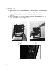
B. A&B C D 14 D. Extract one of the drive trays by pinching the ends of the tray and insert your device click into the bay. Using the 2.5" drive screws (D in Section 1.3), secure your 2.5" drive on the tray so that your drive is secure to the tray with the 2.5" tray holes. Now that the holes line up with a screwdriver. To install a 2.5" drive: A. C. You will hear your drive into place. Place your 3.5" drive to the tray, pinch the ends of the tray inward and pulling the drive tray out.
B. A&B C D 14 D. Extract one of the drive trays by pinching the ends of the tray and insert your device click into the bay. Using the 2.5" drive screws (D in Section 1.3), secure your 2.5" drive on the tray so that your drive is secure to the tray with the 2.5" tray holes. Now that the holes line up with a screwdriver. To install a 2.5" drive: A. C. You will hear your drive into place. Place your 3.5" drive to the tray, pinch the ends of the tray inward and pulling the drive tray out.
User Manual
Page 17
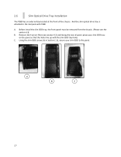
C. Before install the slim ODD tray, the front panel must be removed from the chassis. (Please see section 4.3) and facing the rear of the chassis. Remove the front air filter (see the section 4.2) B. A B C 17 2.6 Slim Optical Drive Tray Installation The P380 has an external bay located at the front of panel, place your slim ODD to the panel. Using the slim ODD screws (G in the tool pack with the slim ODD tray holes. And the slim optical drive tray is attached in Section 1.3), secure your slim ODD tray on the panel so that the holes line up with P380 A.
C. Before install the slim ODD tray, the front panel must be removed from the chassis. (Please see section 4.3) and facing the rear of the chassis. Remove the front air filter (see the section 4.2) B. A B C 17 2.6 Slim Optical Drive Tray Installation The P380 has an external bay located at the front of panel, place your slim ODD to the panel. Using the slim ODD screws (G in the tool pack with the slim ODD tray holes. And the slim optical drive tray is attached in Section 1.3), secure your slim ODD tray on the panel so that the holes line up with P380 A.

User Manual
Page 19
Section 3 Front I/O Ports P380 User Manual 19
Section 3 Front I/O Ports P380 User Manual 19
User Manual
Page 20
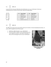
...access USB 3.0 capability from the front panel: 1. Check your motherboard. 20 Identify the USB 3.0 header on your motherboard. Connect the USB 3.0 header to the motherboard port. Align the connector properly to prevent damage to your motherboard user's manual... 7 Ground1 9 Key(No Connection) Pin Signal Names 2 USBPower2 4 NegativeSignal2 6 PositiveSignal2 8 Ground2 10 Empty Pin 3.2 USB 3.0 The P380 comes with two front panel USB 3.0 ports and includes an internal motherboard connector. 3.1 USB 2.0 Connect the front I/O panel USB cable to the USB header pin on...
...access USB 3.0 capability from the front panel: 1. Check your motherboard. 20 Identify the USB 3.0 header on your motherboard. Connect the USB 3.0 header to the motherboard port. Align the connector properly to prevent damage to your motherboard user's manual... 7 Ground1 9 Key(No Connection) Pin Signal Names 2 USBPower2 4 NegativeSignal2 6 PositiveSignal2 8 Ground2 10 Empty Pin 3.2 USB 3.0 The P380 comes with two front panel USB 3.0 ports and includes an internal motherboard connector. 3.1 USB 2.0 Connect the front I/O panel USB cable to the USB header pin on...
User Manual
Page 21
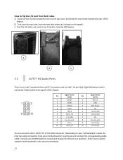
...located on your system supports both sides A. C. Locate the internal audio connectors from both standards, only use one connector. 21 Even if your motherboard. B. Consult your motherboard or sound card and connect the corresponding audio cable. A B C 3.3 AC'97 / HD Audio Ports There is an Intel...® standard 10-pin AC'97 connector and an Intel® 10-pin HDA (High Definition Audio) connector linked to flip the I /O cable out, and screw it shows...
...located on your system supports both sides A. C. Locate the internal audio connectors from both standards, only use one connector. 21 Even if your motherboard. B. Consult your motherboard or sound card and connect the corresponding audio cable. A B C 3.3 AC'97 / HD Audio Ports There is an Intel...® standard 10-pin AC'97 connector and an Intel® 10-pin HDA (High Definition Audio) connector linked to flip the I /O cable out, and screw it shows...

User Manual
Page 22
...manual for specific pin header locations. If the LED does not light up on connecting LEDs to your motherboard, see your motherboard user's manual. Front panel headers Determine which wires you need to remove in order to rewire your plug to match the USB pin-outs on , try reversing the connection...the system is powered on your motherboard (refer to your motherboard user's manual). Attach these to easily slide out the pins from the USB plug. 22 3.4 Power Switch / Reset Switch / Hard Disk Drive LED Connectors Connected to your front panel are LED leads for power and HDD activity, as ...
...manual for specific pin header locations. If the LED does not light up on connecting LEDs to your motherboard, see your motherboard user's manual. Front panel headers Determine which wires you need to remove in order to rewire your plug to match the USB pin-outs on , try reversing the connection...the system is powered on your motherboard (refer to your motherboard user's manual). Attach these to easily slide out the pins from the USB plug. 22 3.4 Power Switch / Reset Switch / Hard Disk Drive LED Connectors Connected to your front panel are LED leads for power and HDD activity, as ...

User Manual
Page 25
The default fan speed setting is Low. 120 mm TwoCool™ fan specifications: Size 120 x 120 x 25 mm two-speed fan Rated Voltage 12V DC Operating Voltage: 12V±10% Speed High 1200RPM ±10% Low 600RPM ±10% Input Current 0.20A 0.10A Airflow 1.208 m³/ ... mm-H2O (0.017 inch-H2O) Noise 27.80 dBA 19.00 dBA Input Power 2.88W 2.88W 25 These fans have two-speed switches that let you choose the speed best suited to your need. 4.1 Included Fans The P380 comes with two standard top 140 mm TwoCool™ fans and a standard rear 120 mm TwoCool™...
The default fan speed setting is Low. 120 mm TwoCool™ fan specifications: Size 120 x 120 x 25 mm two-speed fan Rated Voltage 12V DC Operating Voltage: 12V±10% Speed High 1200RPM ±10% Low 600RPM ±10% Input Current 0.20A 0.10A Airflow 1.208 m³/ ... mm-H2O (0.017 inch-H2O) Noise 27.80 dBA 19.00 dBA Input Power 2.88W 2.88W 25 These fans have two-speed switches that let you choose the speed best suited to your need. 4.1 Included Fans The P380 comes with two standard top 140 mm TwoCool™ fans and a standard rear 120 mm TwoCool™...
User Manual
Page 26
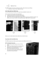
... 1.3). Top exhaust 120 mm/140mm fans The P380 includes three 120mm top fan mounts or two 140mm top fan mounts How to remove the front panel and install the fan A. B. D. Use flathead screwdriver to three more fans. Screw off two screws located on the fan. Align your fan into place. 26 4.2 Optional Fans The P380 includes mounts for up to pull...
... 1.3). Top exhaust 120 mm/140mm fans The P380 includes three 120mm top fan mounts or two 140mm top fan mounts How to remove the front panel and install the fan A. B. D. Use flathead screwdriver to three more fans. Screw off two screws located on the fan. Align your fan into place. 26 4.2 Optional Fans The P380 includes mounts for up to pull...
User Manual
Page 27
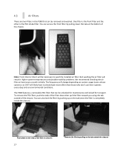
Not washing the air filter will result in the P380 that can be removed and washed. To remove the PSU filter, push the ends of the filter down on the ends of the chassis. You can access the front filter by pulling down the tabs at least once a month initially. Push down then pull the... filter to wash the installed air filter. One filter is the front filter and the other is completely inside the chassis). Note: From time to time it will likely have to check/wash more often than those who don't use their systems every day) and on system usage (users whose systems run...
Not washing the air filter will result in the P380 that can be removed and washed. To remove the PSU filter, push the ends of the filter down on the ends of the chassis. You can access the front filter by pulling down the tabs at least once a month initially. Push down then pull the... filter to wash the installed air filter. One filter is the front filter and the other is completely inside the chassis). Note: From time to time it will likely have to check/wash more often than those who don't use their systems every day) and on system usage (users whose systems run...

