
User Manual
Page 6
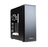
... screw (24) E. 3.5" tray-mount screw (32) F. 1.2 Chassis Specifications Chassis Type Chassis Color Dimensions Weight Cooling Drive Bays Expansion Slots Motherboard Size Front I/O Panel Full Tower Black 21.85" (H) x 8.80" (W) x 21.92" (D) 555 mm (H) x 223.6 mm (W) x 557 mm (D) 27 lbs / 12.25 kg - 3 x 120mm/2 x 140mm top exhaust fan mount(2 x 140mm FDB fan...
... screw (24) E. 3.5" tray-mount screw (32) F. 1.2 Chassis Specifications Chassis Type Chassis Color Dimensions Weight Cooling Drive Bays Expansion Slots Motherboard Size Front I/O Panel Full Tower Black 21.85" (H) x 8.80" (W) x 21.92" (D) 555 mm (H) x 223.6 mm (W) x 557 mm (D) 27 lbs / 12.25 kg - 3 x 120mm/2 x 140mm top exhaust fan mount(2 x 140mm FDB fan...

User Manual
Page 22
... connector at a time, use a very small flathead screwdriver or similar tool to lift up when the system is powered on the black tab located beside the gold posts (squares). White or black wires are positive ( + ). If the LED does not light up on , try reversing the connection. 3.4 Power Switch / Reset Switch / Hard...
... connector at a time, use a very small flathead screwdriver or similar tool to lift up when the system is powered on the black tab located beside the gold posts (squares). White or black wires are positive ( + ). If the LED does not light up on , try reversing the connection. 3.4 Power Switch / Reset Switch / Hard...

User Manual
Page 23
Working carefully so as not to damage the wires, connectors, or pins, slowly remove the pin from the connector. Repeat these steps for each wire you need to change . 23 Working carefully so as not to damage the wires, connectors or pins, slowly insert the pin into the correct slot of the connector then snap closed the black tab that was lifted in step 1. Repeat these steps for each wire you need to change .
Working carefully so as not to damage the wires, connectors, or pins, slowly remove the pin from the connector. Repeat these steps for each wire you need to change . 23 Working carefully so as not to damage the wires, connectors or pins, slowly insert the pin into the correct slot of the connector then snap closed the black tab that was lifted in step 1. Repeat these steps for each wire you need to change .