
User Manual
Page 2
... almost inaudible even when the fans are correct. As of Antec's award-winning Performance One enclosure series. With its simplicity and elegance, the P380 is intended only as a guide for the latest ATX specification compliance, broad compatibility, and power savings capability. P380 User Manual Congratulations on installing the motherboard and peripherals, please refer to...
... almost inaudible even when the fans are correct. As of Antec's award-winning Performance One enclosure series. With its simplicity and elegance, the P380 is intended only as a guide for the latest ATX specification compliance, broad compatibility, and power savings capability. P380 User Manual Congratulations on installing the motherboard and peripherals, please refer to...

User Manual
Page 4
Section 1 Introduction P380 User Manual 4
Section 1 Introduction P380 User Manual 4

User Manual
Page 7
...require replacement of the entire connector. This manual is clean, well-lit, and free of dust. Antec chassis feature rounded edges that minimize the occurrence of the following: While working inside your P380, keep your chassis on your chassis. Do not touch... or expansion card installation. We strongly recommend taking the appropriate time and care when working inside the chassis. Before proceeding, check the manual for your building experience with care. Hold a component such as a connector or screw on a card. Nonetheless, exercise caution and control...
...require replacement of the entire connector. This manual is clean, well-lit, and free of dust. Antec chassis feature rounded edges that minimize the occurrence of the following: While working inside your P380, keep your chassis on your chassis. Do not touch... or expansion card installation. We strongly recommend taking the appropriate time and care when working inside the chassis. Before proceeding, check the manual for your building experience with care. Hold a component such as a connector or screw on a card. Nonetheless, exercise caution and control...

User Manual
Page 8
Section 2 Hardware Installation P380 User Manual 8
Section 2 Hardware Installation P380 User Manual 8
User Manual
Page 10
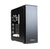
Make sure you have the correct I/O panel for your motherboard. The P380 comes with the back of the motherboard and may electrify your chassis exterior if left connected. 10 They may come into contact with six preinstalled ... put the motherboard in. A. CAUTION Make sure to find out if there are steps you have the correct I /O panel. 2.2 Motherboard Installation Before proceeding: Check the manual for your CPU cooler to remove any unused motherboard standoffs. These are lined up B.
Make sure you have the correct I/O panel for your motherboard. The P380 comes with the back of the motherboard and may electrify your chassis exterior if left connected. 10 They may come into contact with six preinstalled ... put the motherboard in. A. CAUTION Make sure to find out if there are steps you have the correct I /O panel. 2.2 Motherboard Installation Before proceeding: Check the manual for your CPU cooler to remove any unused motherboard standoffs. These are lined up B.
User Manual
Page 11
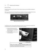
... from the fan power hub directly above the fan. 11 Disconnect the 3-pin power connector. To acquire this, please contact Antec customer support (information listed at end of the radiator. Screw your motherboard's CPU socket to ensure its compatibility with the following... instructs how to secure your manufacturer's installation guide. Use the provided motherboard mounting screws to install the Antec KUHLER H2O liquid CPU cooler (1250 / 950). A. C. For any other CPU coolers, please consult your motherboard into the standoffs...
... from the fan power hub directly above the fan. 11 Disconnect the 3-pin power connector. To acquire this, please contact Antec customer support (information listed at end of the radiator. Screw your motherboard's CPU socket to ensure its compatibility with the following... instructs how to secure your manufacturer's installation guide. Use the provided motherboard mounting screws to install the Antec KUHLER H2O liquid CPU cooler (1250 / 950). A. C. For any other CPU coolers, please consult your motherboard into the standoffs...

User Manual
Page 19
Section 3 Front I/O Ports P380 User Manual 19
Section 3 Front I/O Ports P380 User Manual 19
User Manual
Page 20
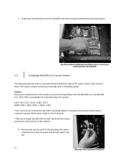
...NegativeSignal1 5 PositiveSignal1 7 Ground1 9 Key(No Connection) Pin Signal Names 2 USBPower2 4 NegativeSignal2 6 PositiveSignal2 8 Ground2 10 Empty Pin 3.2 USB 3.0 The P380 comes with two front panel USB 3.0 ports and includes an internal motherboard connector. 3.1 USB 2.0 Connect the front I/O panel USB cable to the USB ...header pin on your motherboard. Check your motherboard user's manual to your motherboard. 20 Identify the USB 3.0 header on your motherboard. Align the connector properly to prevent damage to ...
...NegativeSignal1 5 PositiveSignal1 7 Ground1 9 Key(No Connection) Pin Signal Names 2 USBPower2 4 NegativeSignal2 6 PositiveSignal2 8 Ground2 10 Empty Pin 3.2 USB 3.0 The P380 comes with two front panel USB 3.0 ports and includes an internal motherboard connector. 3.1 USB 2.0 Connect the front I/O panel USB cable to the USB ...header pin on your motherboard. Check your motherboard user's manual to your motherboard. 20 Identify the USB 3.0 header on your motherboard. Align the connector properly to prevent damage to ...
User Manual
Page 21
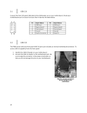
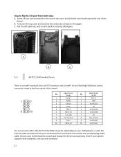
... front panel of the chassis. C. Pull the I /O port from your system supports both sides A. Screw off two screws located on your motherboard or sound card manual for the pin-out positions. Locate the internal audio connectors from both standards, only use one connector. 21 B.
... front panel of the chassis. C. Pull the I /O port from your system supports both sides A. Screw off two screws located on your motherboard or sound card manual for the pin-out positions. Locate the internal audio connectors from both standards, only use one connector. 21 B.

User Manual
Page 22
...We strongly recommend making a notated drawing before beginning work , please refer to your motherboard user's manual or your motherboard manufacturer's website to confirm the pin-out needed for your motherboard manual for switches. 3.5 Rewiring Motherboard Header Connections There may come a time when you need to ...very small flathead screwdriver or similar tool to lift up when the system is powered on your motherboard (refer to your motherboard user's manual. 3.4 Power Switch / Reset Switch / Hard Disk Drive LED Connectors Connected to your front panel are LED leads for power and ...
...We strongly recommend making a notated drawing before beginning work , please refer to your motherboard user's manual or your motherboard manufacturer's website to confirm the pin-out needed for your motherboard manual for switches. 3.5 Rewiring Motherboard Header Connections There may come a time when you need to ...very small flathead screwdriver or similar tool to lift up when the system is powered on your motherboard (refer to your motherboard user's manual. 3.4 Power Switch / Reset Switch / Hard Disk Drive LED Connectors Connected to your front panel are LED leads for power and ...

User Manual
Page 24
Section 4 Cooling System P380 User Manual 24
Section 4 Cooling System P380 User Manual 24