Manual
Page 2
... on your new case will differ slightly from the descriptions in this manual. Sonata IV is intended only as a guide for Antec's computer enclosures. it's simply an improvement. This isn't a problem; SONATA IV USER'S MANUAL Congratulations on installing the motherboard and peripherals, please refer to the user's manuals that allows for maximum cooling with those components. 1 Disclaimer This...
... on your new case will differ slightly from the descriptions in this manual. Sonata IV is intended only as a guide for Antec's computer enclosures. it's simply an improvement. This isn't a problem; SONATA IV USER'S MANUAL Congratulations on installing the motherboard and peripherals, please refer to the user's manuals that allows for maximum cooling with those components. 1 Disclaimer This...

Manual
Page 6
... which holes are planning to the standoffs with the provided Philips-head screws. Installing a 3.5" drive first will not affect functionality. 4. 2.2 Motherboard Installation This manual does not cover CPU, RAM or expansion card installation. Not all the provided holes; Your motherboard is a space to secure the drive. 5 To the left... the screws for the correct I /O panel for your motherboard. If the panel provided with your motherboard manufacturer for a 2.5" drive. Fasten your motherboard manual for 2.5 HDD". Use these screws to mount a 2.5" drive.
... which holes are planning to the standoffs with the provided Philips-head screws. Installing a 3.5" drive first will not affect functionality. 4. 2.2 Motherboard Installation This manual does not cover CPU, RAM or expansion card installation. Not all the provided holes; Your motherboard is a space to secure the drive. 5 To the left... the screws for the correct I /O panel for your motherboard. If the panel provided with your motherboard manufacturer for a 2.5" drive. Fasten your motherboard manual for 2.5 HDD". Use these screws to mount a 2.5" drive.

Manual
Page 8
... into the motherboard compartment, the cables can be organized between the motherboard and right side panel. 1. Choose the cables you hear a click. 4. Check the motherboard manual to hold them in place. Remove both side panels. 2. Run the cables to the organizer and use the cable ties to ensure that it matches...
... into the motherboard compartment, the cables can be organized between the motherboard and right side panel. 1. Choose the cables you hear a click. 4. Check the motherboard manual to hold them in place. Remove both side panels. 2. Run the cables to the organizer and use the cable ties to ensure that it matches...

Manual
Page 9
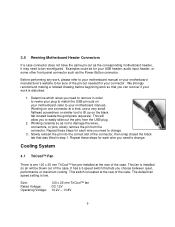
...panel USB 3.0 port. For LEDs, colored wires are LED and switch leads for the pin-out positions. Even if your motherboard manual. Note: Polarity (positive and negative) does not matter for specific pin header locations. Attach these to your motherboard, see your...White or black wires are negative ( - ). Consult your motherboard. For more information on connecting LEDs to the corresponding connectors on your motherboard or sound card manual for power, reset, HDD and Power LED activity. Pin Signal Names (HDA) Pin Signal Names (AC'97) 1 MIC2 L 1 MIC In 2 AGND...
...panel USB 3.0 port. For LEDs, colored wires are LED and switch leads for the pin-out positions. Even if your motherboard manual. Note: Polarity (positive and negative) does not matter for specific pin header locations. Attach these to your motherboard, see your...White or black wires are negative ( - ). Consult your motherboard. For more information on connecting LEDs to the corresponding connectors on your motherboard or sound card manual for power, reset, HDD and Power LED activity. Pin Signal Names (HDA) Pin Signal Names (AC'97) 1 MIC2 L 1 MIC In 2 AGND...
Manual
Page 10
...connector, then snap closed the black tab that was lifted in order to rewire your plug to match the USB pin-outs on your motherboard manual). Working on the black tab located beside the gold posts (squares). Slowly reinsert the pin into the correct slot of the pin-out ...'s website to change . 3. This fan is one connector at the rear of the case. Before performing any work, please refer to your motherboard manual or your connector. We strongly recommend making a notated drawing before beginning work is low. Repeat these steps for your work so that lets you can...
...connector, then snap closed the black tab that was lifted in order to rewire your plug to match the USB pin-outs on your motherboard manual). Working on the black tab located beside the gold posts (squares). Slowly reinsert the pin into the correct slot of the pin-out ...'s website to change . 3. This fan is one connector at the rear of the case. Before performing any work, please refer to your motherboard manual or your connector. We strongly recommend making a notated drawing before beginning work is low. Repeat these steps for your work so that lets you can...