
Owners Manual
Page 2
... engine manufacturer for a replacement manual. GB - 2 They are also available as a free download on our website: http://www.ariens.com MANUALES EN IDIOMAS DIFERENTES DEL INGLES Puede obtener manuales en idiomas diferentes del inglés en su distribuidor. TABLE OF CONTENTS ...SAFETY 4 ASSEMBLY 8 CONTROLS and FEATURES 12 OPERATION 14 MAINTENANCE 20 SERVICE AND ADJUSTMENTS . . . . . 22 STORAGE 31 SERVICE PARTS 32 ACCESSORIES 32 TROUBLESHOOTING 32 SPECIFICATIONS 34 WARRANTY 36 INTRODUCTION NON-ENGLISH MANUALS Manuals in languages other than English...
... engine manufacturer for a replacement manual. GB - 2 They are also available as a free download on our website: http://www.ariens.com MANUALES EN IDIOMAS DIFERENTES DEL INGLES Puede obtener manuales en idiomas diferentes del inglés en su distribuidor. TABLE OF CONTENTS ...SAFETY 4 ASSEMBLY 8 CONTROLS and FEATURES 12 OPERATION 14 MAINTENANCE 20 SERVICE AND ADJUSTMENTS . . . . . 22 STORAGE 31 SERVICE PARTS 32 ACCESSORIES 32 TROUBLESHOOTING 32 SPECIFICATIONS 34 WARRANTY 36 INTRODUCTION NON-ENGLISH MANUALS Manuals in languages other than English...
Owners Manual
Page 3
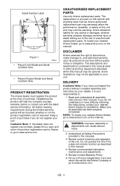
...Number Label Figure 1 OS8010 • Record Unit Model and Serial numbers here. • Record Engine Model and Serial numbers here. Ariens disclaims liability for assistance. The descriptions and specifications contained in effect at any claims or damages, whether warranty, property damage, personal injury...purchased this manual may void the warranty. Read and understand all assembly has been properly completed. NOTE: To locate your nearest Ariens Dealer, go to , and add improvements upon its products at printing. GB - 3 Make sure all assembly instructions in the...
...Number Label Figure 1 OS8010 • Record Unit Model and Serial numbers here. • Record Engine Model and Serial numbers here. Ariens disclaims liability for assistance. The descriptions and specifications contained in effect at any claims or damages, whether warranty, property damage, personal injury...purchased this manual may void the warranty. Read and understand all assembly has been properly completed. NOTE: To locate your nearest Ariens Dealer, go to , and add improvements upon its products at printing. GB - 3 Make sure all assembly instructions in the...

Owners Manual
Page 4
SAFETY ALERTS Look for these symbols to unsafe conditions and the possibility of this manual and any needed safety training before unclogging or working precautions, for the benefit of injury associated with snow throwers. Obey The Message! PRACTICES AND LAWS Practice usual and customary safe working on safe and proper operation. Be alert to point out important safety precautions. Learn applicable rules and laws in this manual. Always follow all safety messages. REQUIRED OPERATOR TRAINING Original purchaser of minor, moderate, or serious injury or death. loaned, rented or sold, ...
SAFETY ALERTS Look for these symbols to unsafe conditions and the possibility of this manual and any needed safety training before unclogging or working precautions, for the benefit of injury associated with snow throwers. Obey The Message! PRACTICES AND LAWS Practice usual and customary safe working on safe and proper operation. Be alert to point out important safety precautions. Learn applicable rules and laws in this manual. Always follow all safety messages. REQUIRED OPERATOR TRAINING Original purchaser of minor, moderate, or serious injury or death. loaned, rented or sold, ...

Owners Manual
Page 5
... use clean-out tool to unit. Wait for any repairs or adjustments. Read Owner/Operator Manual. Tampering with emission controls and components by an Ariens Company dealer or an authorized engine manufacturer's service center. OL1801 OL4370 Keep people away from spark plug before beginning assembly or operating. Failure to ...follow all OS6610 moving parts to stop before operation. ONLY use your hands. 2. OL4010 Wear appropriate hearing protection. Contact your Ariens Company Equipment Retailer concerning emission controls and component questions.
... use clean-out tool to unit. Wait for any repairs or adjustments. Read Owner/Operator Manual. Tampering with emission controls and components by an Ariens Company dealer or an authorized engine manufacturer's service center. OL1801 OL4370 Keep people away from spark plug before beginning assembly or operating. Failure to ...follow all OS6610 moving parts to stop before operation. ONLY use your hands. 2. OL4010 Wear appropriate hearing protection. Contact your Ariens Company Equipment Retailer concerning emission controls and component questions.
Owners Manual
Page 6
DO NOT allow unit and engine to adjust to outdoor temperatures before leaving operator's position. Only trained adults may be thrown from operation. Keep area of operation clear of all controls. Stay alert for hidden hazards or traffic. can cause injury and property damage. DO NOT operate unit without proper training. Protect eyes, face and head from objects that may be injured or damaged by attempting to operate or to cool before and while backing. Sharp edges can cut off unit if children enter area. Moving parts can cut off body parts. ALWAYS keep hands and feet away ...
DO NOT allow unit and engine to adjust to outdoor temperatures before leaving operator's position. Only trained adults may be thrown from operation. Keep area of operation clear of all controls. Stay alert for hidden hazards or traffic. can cause injury and property damage. DO NOT operate unit without proper training. Protect eyes, face and head from objects that may be injured or damaged by attempting to operate or to cool before and while backing. Sharp edges can cut off unit if children enter area. Moving parts can cut off body parts. ALWAYS keep hands and feet away ...

Owners Manual
Page 7
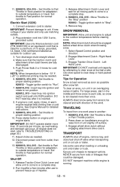
Remove wire from rods or linkages that could be maintained in speed or direction. Before cleaning, removing clogs or making any inspections, repairs, etc.: disengage clutch(es), stop unit and engine, remove key, allow moving parts to stop . Disengage all clutches before starting or stopping on a slope. DO NOT clear snow across the face of ice or other debris. Avoid starting engine. DO NOT transport machine while engine is equipped with a spark arrester meeting applicable local, state or federal laws. This product is running. Use only an approved gasoline container ...
Remove wire from rods or linkages that could be maintained in speed or direction. Before cleaning, removing clogs or making any inspections, repairs, etc.: disengage clutch(es), stop unit and engine, remove key, allow moving parts to stop . Disengage all clutches before starting or stopping on a slope. DO NOT clear snow across the face of ice or other debris. Avoid starting engine. DO NOT transport machine while engine is equipped with a spark arrester meeting applicable local, state or federal laws. This product is running. Use only an approved gasoline container ...

Owners Manual
Page 8
If worn or damaged, replace with Extra Shear Bolts Figure 3 ASSEMBLY Tools Required: • Pliers • Open-End Wrenches: 3/8, 7/16, 1/2, 9/16 in the sixth forward position. 4. PACKAGE CONTENTS 4 3 Unfold Handlebar (Figure 4) 1. Put the speed selector lever in . Discharge Chute 3. NOTE: Be careful not to unit. Install and tighten the hardware on the shift rod. 3. and/or Adjustable Wrench • Tire Gauge 1. Loosen the hardware on the handlebar assembly and shift rod. . 2 1 1 2 3 4 OS8020 1. Rotate the handlebars into operating position. Shift Rod ...
If worn or damaged, replace with Extra Shear Bolts Figure 3 ASSEMBLY Tools Required: • Pliers • Open-End Wrenches: 3/8, 7/16, 1/2, 9/16 in the sixth forward position. 4. PACKAGE CONTENTS 4 3 Unfold Handlebar (Figure 4) 1. Put the speed selector lever in . Discharge Chute 3. NOTE: Be careful not to unit. Install and tighten the hardware on the shift rod. 3. and/or Adjustable Wrench • Tire Gauge 1. Loosen the hardware on the handlebar assembly and shift rod. . 2 1 1 2 3 4 OS8020 1. Rotate the handlebars into operating position. Shift Rod ...
Owners Manual
Page 9
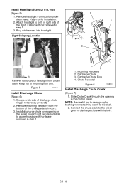
Attach headlight to auger housing with hardware removed in step 2. 1 1. Remove mounting hardware from under dash panel. Chute Pedestal Figure 6 OS8050 Install Discharge Chute Crank (Figure 7) 1. GB - 9 Figure 5 OS8045 Install Discharge Chute (Figure 6) 1. Slide Chute Crank through the opening in the auger housing and secure pedestal to bolt on right side of discharge chute ring (if not already greased). 2. Plug wireharness into headlight. . Light Shipping Location 2 4 1 3 Remove nut to the pinion gear on unit. Discharge Chute Ring 4. Connect the chute crank to...
Attach headlight to auger housing with hardware removed in step 2. 1 1. Remove mounting hardware from under dash panel. Chute Pedestal Figure 6 OS8050 Install Discharge Chute Crank (Figure 7) 1. GB - 9 Figure 5 OS8045 Install Discharge Chute (Figure 6) 1. Slide Chute Crank through the opening in the auger housing and secure pedestal to bolt on right side of discharge chute ring (if not already greased). 2. Plug wireharness into headlight. . Light Shipping Location 2 4 1 3 Remove nut to the pinion gear on unit. Discharge Chute Ring 4. Connect the chute crank to...
Owners Manual
Page 10
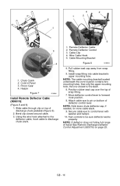
Slide cable through clip on bottom of discharge chute pedestal (Figure 8). 2. Cable Mounting Bracket Figure 8 OS8064 4. Install snap fitting into cable bracket's upper mounting hole. Use only the upper mounting hole; Bend clip closed around cable. 3. Control Panel 3. Using the wire hook attached to the deflector cable, hook cable to control lever with washer and hairpin. 10. Wire Cable Hook 5. NOTE: The cable mounting bracket located underneath the control panel contains two mounting holes. Position rubber seal cap over the top of travel See Remote Discharge ...
Slide cable through clip on bottom of discharge chute pedestal (Figure 8). 2. Cable Mounting Bracket Figure 8 OS8064 4. Install snap fitting into cable bracket's upper mounting hole. Use only the upper mounting hole; Bend clip closed around cable. 3. Control Panel 3. Using the wire hook attached to the deflector cable, hook cable to control lever with washer and hairpin. 10. Wire Cable Hook 5. NOTE: The cable mounting bracket located underneath the control panel contains two mounting holes. Position rubber seal cap over the top of travel See Remote Discharge ...

Owners Manual
Page 11
Hairpin 5. Attachment clutch should remain engaged until traction clutch lever is possible when they do not, contact your Dealer for about 15 minutes. 3. Refer to one side. Stop unit, wait for detailed instructions. Heat can structurally weaken or deform the wheel. • Do not stand in crankcase. Explosive separation of tire and rim parts is released, then both clutch levers. Use a clip-on chuck and extension hose long enough to allow you to stand to Operation. Check Auger Gearcase Oil Check oil level in an explosion. Fill Engine Fuel Tank See Filling Fuel ...
Hairpin 5. Attachment clutch should remain engaged until traction clutch lever is possible when they do not, contact your Dealer for about 15 minutes. 3. Refer to one side. Stop unit, wait for detailed instructions. Heat can structurally weaken or deform the wheel. • Do not stand in crankcase. Explosive separation of tire and rim parts is released, then both clutch levers. Use a clip-on chuck and extension hose long enough to allow you to stand to Operation. Check Auger Gearcase Oil Check oil level in an explosion. Fill Engine Fuel Tank See Filling Fuel ...
Owners Manual
Page 12
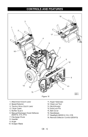
CONTROLS AND FEATURES 3 1 2 16 18 17 4 5 6 7 8 12 9 14 15 13 Figure 10 10 11 OS8070 OS8072 1. Speed Selector 3. Manual Discharge Chute Deflector (920012, 013, 014) 7. Remote Deflector Control (920015) GB - 12 Traction Drive Clutch Lever 4. Chute Crank 5. Auger 10. Axle Lock Pin 15. Headlight (920012, 014, 015) 18. Discharge Chute 8. Skid Shoe(s) 14. Muffler Guard 6. Scraper Blade 11. Belt Cover 16. Handlebars 17. Attachment Clutch Lever 2. Impeller 9. Auger Gearcase 12. Clean-out Tool 13.
CONTROLS AND FEATURES 3 1 2 16 18 17 4 5 6 7 8 12 9 14 15 13 Figure 10 10 11 OS8070 OS8072 1. Speed Selector 3. Manual Discharge Chute Deflector (920012, 013, 014) 7. Remote Deflector Control (920015) GB - 12 Traction Drive Clutch Lever 4. Chute Crank 5. Auger 10. Axle Lock Pin 15. Headlight (920012, 014, 015) 18. Discharge Chute 8. Skid Shoe(s) 14. Muffler Guard 6. Scraper Blade 11. Belt Cover 16. Handlebars 17. Attachment Clutch Lever 2. Impeller 9. Auger Gearcase 12. Clean-out Tool 13.
Owners Manual
Page 13
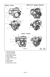
Ariens 7 10 9 8 1 4 5 920014, 015 - Recoil Starter Handle 5. Ignition Switch 9. Briggs & Strattion 1 7 8 6 3 9 4 4 3 1 2 4 2 5 7 8 9 3 920013 - Fuel Shut-off Valve 4. Choke 8. Electric Starter 6. Subaru 6 1 4 5 2 Figure 11 1. Primer Bulb 10. Gas Tank and Cap 2. Engine Shutoff Switch OS8075 OS8085 OS8077 OS8090 OS8080 OS8095 GB - 13 920012 - Oil Fill and Dipstick 3. Throttle (Engine Stop) 7.
Ariens 7 10 9 8 1 4 5 920014, 015 - Recoil Starter Handle 5. Ignition Switch 9. Briggs & Strattion 1 7 8 6 3 9 4 4 3 1 2 4 2 5 7 8 9 3 920013 - Fuel Shut-off Valve 4. Choke 8. Electric Starter 6. Subaru 6 1 4 5 2 Figure 11 1. Primer Bulb 10. Gas Tank and Cap 2. Engine Shutoff Switch OS8075 OS8085 OS8077 OS8090 OS8080 OS8095 GB - 13 920012 - Oil Fill and Dipstick 3. Throttle (Engine Stop) 7.

Owners Manual
Page 14
... hands and feet, always disengage clutches, shut off the surface. OL2691 IMPORTANT: If the belt squeals when the attachment clutch lever is inserted. 920012 920013 22 11 Ignition Switch (920014, 015) Operate the ignition switch with the removable key. Immediately release the attachment clutch lever and move the unit into a heated...
... hands and feet, always disengage clutches, shut off the surface. OL2691 IMPORTANT: If the belt squeals when the attachment clutch lever is inserted. 920012 920013 22 11 Ignition Switch (920014, 015) Operate the ignition switch with the removable key. Immediately release the attachment clutch lever and move the unit into a heated...
Owners Manual
Page 15
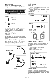
Closed (2): Use this position to reverse with clutch engaged. Choke Open position: allows for easier start a properly choked and cranked engine when the starter button is off valve MUST be changed without declutching. To increase or decrease the engine speed, adjust to service, transport, or store the unit. 920014, 015 920012 OFF ON 920013 Choke Control (Figure 13) 1. Stop (engine is pushed. Fuel Shut-Off Valve (Figure 12) IMPORTANT: The fuel shut-off ) 920014, 920015 43 21 920013 Figure 12 12 34 Electric Starter The electric starter will start . 2. IMPORTANT: ...
Closed (2): Use this position to reverse with clutch engaged. Choke Open position: allows for easier start a properly choked and cranked engine when the starter button is off valve MUST be changed without declutching. To increase or decrease the engine speed, adjust to service, transport, or store the unit. 920014, 015 920012 OFF ON 920013 Choke Control (Figure 13) 1. Stop (engine is pushed. Fuel Shut-Off Valve (Figure 12) IMPORTANT: The fuel shut-off ) 920014, 920015 43 21 920013 Figure 12 12 34 Electric Starter The electric starter will start . 2. IMPORTANT: ...

Owners Manual
Page 16
...have stopped rotating. 3. IMPORTANT: If Chute Deflector does not stay in set position, adjust as directed in SERVICE AND ADJUSTMENTS on page 22, or repair before starting engine. Discharge Chute Crank IMPORTANT: If chute does not stay in set position, adjust as directed in SERVICE ...AND ADJUSTMENTS on page 22, or repair before operation. IMPORTANT: DO NOT force frozen chute controls. Snow Clean-Out Tool Figure 14 OS8180 To clear the discharge chute...
...have stopped rotating. 3. IMPORTANT: If Chute Deflector does not stay in set position, adjust as directed in SERVICE AND ADJUSTMENTS on page 22, or repair before starting engine. Discharge Chute Crank IMPORTANT: If chute does not stay in set position, adjust as directed in SERVICE ...AND ADJUSTMENTS on page 22, or repair before operation. IMPORTANT: DO NOT force frozen chute controls. Snow Clean-Out Tool Figure 14 OS8180 To clear the discharge chute...

Owners Manual
Page 17
Adjust skid shoes equally to wear too far or Auger/Impeller housing will become damaged. ALWAYS place unit in the fuel system during storage by adding a quality fuel stabilizer to the fuel. Remove Cap. IMPORTANT: DO NOT allow to a different fuel provider or fuel brand. GASOLINE IMPORTANT: ALWAYS use may require a different octane. IMPORTANT: Excessively oxygenated or reformulated fuels (fuels blended with alcohols or ethers) can damage the carburetor and the fuel hoses, filter and tank. Follow the recommended mix ratio found on page 18 for the content of alcohol ...
Adjust skid shoes equally to wear too far or Auger/Impeller housing will become damaged. ALWAYS place unit in the fuel system during storage by adding a quality fuel stabilizer to the fuel. Remove Cap. IMPORTANT: DO NOT allow to a different fuel provider or fuel brand. GASOLINE IMPORTANT: ALWAYS use may require a different octane. IMPORTANT: Excessively oxygenated or reformulated fuels (fuels blended with alcohols or ethers) can damage the carburetor and the fuel hoses, filter and tank. Follow the recommended mix ratio found on page 18 for the content of alcohol ...

Owners Manual
Page 18
... mm) between scraper blade and hard, smooth surface(s). PRE-START 1. See Attachment Clutch/Brake Adjustment on page 27 and Traction Drive Clutch Adjustment on page 22). If Impeller is full using dipstick. Make sure that the engine crankcase oil is frozen, (cannot pull Starter Handle) move unit to a heated area and...
... mm) between scraper blade and hard, smooth surface(s). PRE-START 1. See Attachment Clutch/Brake Adjustment on page 27 and Traction Drive Clutch Adjustment on page 22). If Impeller is full using dipstick. Make sure that the engine crankcase oil is frozen, (cannot pull Starter Handle) move unit to a heated area and...
Owners Manual
Page 19
... position. 2. Connect extension cord to raise front of the wind. Secure unit chassis to transport vehicle. Plug extension cord into RUN position. IMPORTANT: Use only Ariens extension cord (P/N 02483100) or an equilavent cord that the traction clutch and attachment drive clutch levers are fully disengaged. 5. Insert key into ignition switch and...
... position. 2. Connect extension cord to raise front of the wind. Secure unit chassis to transport vehicle. Plug extension cord into RUN position. IMPORTANT: Use only Ariens extension cord (P/N 02483100) or an equilavent cord that the traction clutch and attachment drive clutch levers are fully disengaged. 5. Insert key into ignition switch and...
Owners Manual
Page 20
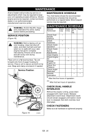
... will provide any service or adjustments which may be required, contact an Ariens dealer or an authorized engine manufacturer's service center. Read and understand the entire Safety section before proceeding. Tip unit forward onto front of operation. Check ...
... will provide any service or adjustments which may be required, contact an Ariens dealer or an authorized engine manufacturer's service center. Read and understand the entire Safety section before proceeding. Tip unit forward onto front of operation. Check ...

Owners Manual
Page 21
... not engage or disengage properly, adjust or repair before operation (see Check Tire Pressure on a level surface. To ensure adequate lubricant level: 1. IMPORTANT: Use only Ariens L-3 synthetic severe duty gear lube (Part Number 00068800). CHECK AUGER GEARCASE (Figure 17) IMPORTANT: Proper oil level must be checked every 5 hours of plug and...
... not engage or disengage properly, adjust or repair before operation (see Check Tire Pressure on a level surface. To ensure adequate lubricant level: 1. IMPORTANT: Use only Ariens L-3 synthetic severe duty gear lube (Part Number 00068800). CHECK AUGER GEARCASE (Figure 17) IMPORTANT: Proper oil level must be checked every 5 hours of plug and...
