
Owners Manual
Page 2
... in the unit literature package. If used improperly, this manual for a replacement manual. MODEL AND SERIAL NUMBERS When ordering replacement parts or making service inquiries, know the Model and Serial numbers of forward travel. TABLE OF CONTENTS SAFETY 4 ASSEMBLY 8 CONTROLS and FEATURES 12 OPERATION 14 MAINTENANCE 20 SERVICE AND ADJUSTMENTS . . . . . 22 STORAGE 31 SERVICE PARTS 32 ACCESSORIES 32 TROUBLESHOOTING 32 SPECIFICATIONS 34 WARRANTY 36 INTRODUCTION NON-ENGLISH MANUALS Manuals in languages other than English may be dangerous...
... in the unit literature package. If used improperly, this manual for a replacement manual. MODEL AND SERIAL NUMBERS When ordering replacement parts or making service inquiries, know the Model and Serial numbers of forward travel. TABLE OF CONTENTS SAFETY 4 ASSEMBLY 8 CONTROLS and FEATURES 12 OPERATION 14 MAINTENANCE 20 SERVICE AND ADJUSTMENTS . . . . . 22 STORAGE 31 SERVICE PARTS 32 ACCESSORIES 32 TROUBLESHOOTING 32 SPECIFICATIONS 34 WARRANTY 36 INTRODUCTION NON-ENGLISH MANUALS Manuals in languages other than English may be dangerous...
Owners Manual
Page 3
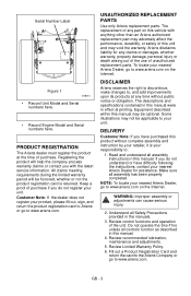
... 1 OS8010 • Record Unit Model and Serial numbers here. • Record Engine Model and Serial numbers here. UNAUTHORIZED REPLACEMENT PARTS Use only Ariens replacement parts. DISCLAIMER Ariens reserves the right to discontinue, make changes to your unit. The descriptions and specifications contained in this manual may not be honored, whether or not the product registration card is your nearest Ariens Dealer, go to www.ariens.com on the Internet...
... 1 OS8010 • Record Unit Model and Serial numbers here. • Record Engine Model and Serial numbers here. UNAUTHORIZED REPLACEMENT PARTS Use only Ariens replacement parts. DISCLAIMER Ariens reserves the right to discontinue, make changes to your unit. The descriptions and specifications contained in this manual may not be honored, whether or not the product registration card is your nearest Ariens Dealer, go to www.ariens.com on the Internet...

Owners Manual
Page 5
... damage to clear blockages. ALWAYS remove key and/or wire from unit while operating. OL1801 OL4370 Keep people away from spark plug before assembly, maintenance or service. High speed impeller rotates below discharge opening. OS2080 ROTATING PARTS. Tampering with emission controls and components by an Ariens Company dealer or an authorized engine manufacturer's service center. GB - 5 Stop engine, remove key, read manual before operation. Read Owner/Operator Manual. OL4010 Wear appropriate hearing...
... damage to clear blockages. ALWAYS remove key and/or wire from unit while operating. OL1801 OL4370 Keep people away from spark plug before assembly, maintenance or service. High speed impeller rotates below discharge opening. OS2080 ROTATING PARTS. Tampering with emission controls and components by an Ariens Company dealer or an authorized engine manufacturer's service center. GB - 5 Stop engine, remove key, read manual before operation. Read Owner/Operator Manual. OL4010 Wear appropriate hearing...
Owners Manual
Page 6
... starting engine, disengage control(s). Always stand clear of your body or clothing inside or near any higher than necessary. Always look down and turn over if a wheel is over the edge of all times. GB - 6 Be alert and shut off body parts. Check for hidden hazards. DO NOT operate unit without proper training. DO NOT run during operation. Use only approved extension cords...
... starting engine, disengage control(s). Always stand clear of your body or clothing inside or near any higher than necessary. Always look down and turn over if a wheel is over the edge of all times. GB - 6 Be alert and shut off body parts. Check for hidden hazards. DO NOT operate unit without proper training. DO NOT run during operation. Use only approved extension cords...

Owners Manual
Page 7
... use . Keep unit free of slopes. NO smoking, NO sparks, NO flames. If this is used, must stop . Before tipping unit up of drive wheels and auger/impeller must be damaged. DO NOT run engine in place and securely fastened. Check shear bolts frequently. Inspect unit and make sudden changes in speed or direction. Disengage all clutches before leaving unit. Never leave a running . Check clutch and brake operation frequently. Avoid starting engine. Use...
... use . Keep unit free of slopes. NO smoking, NO sparks, NO flames. If this is used, must stop . Before tipping unit up of drive wheels and auger/impeller must be damaged. DO NOT run engine in place and securely fastened. Check shear bolts frequently. Inspect unit and make sudden changes in speed or direction. Disengage all clutches before leaving unit. Never leave a running . Check clutch and brake operation frequently. Avoid starting engine. Use...

Owners Manual
Page 8
... damage cable spring hooks when rotating handlebars upward. 5. Sno-Thro Unit 2. Discharge Chute 3. Shift Rod 2. Check components frequently. PACKAGE CONTENTS 4 3 Unfold Handlebar (Figure 4) 1. NOTE: Be careful not to unit. Install and tighten the hardware on the handlebar assembly. 2. Shift Rod Hardware 4. ASSEMBLY WARNING: AVOID INJURY. Rotate the handlebars into operating position. If worn or damaged, replace with Extra Shear Bolts Figure 3 ASSEMBLY Tools Required...
... damage cable spring hooks when rotating handlebars upward. 5. Sno-Thro Unit 2. Discharge Chute 3. Shift Rod 2. Check components frequently. PACKAGE CONTENTS 4 3 Unfold Handlebar (Figure 4) 1. NOTE: Be careful not to unit. Install and tighten the hardware on the handlebar assembly. 2. Shift Rod Hardware 4. ASSEMBLY WARNING: AVOID INJURY. Rotate the handlebars into operating position. If worn or damaged, replace with Extra Shear Bolts Figure 3 ASSEMBLY Tools Required...

Owners Manual
Page 11
... 5. Check Auger Gearcase Oil Check oil level in crankcase. Refer to Engine Manual for about 15 minutes. 3. . 2 1 5 6 4 3 1. Cable Eye Figure 9 OS8066 Check Function of all moving parts to stop, and remove spark plug wire. 4. Check Engine Crankcase Oil IMPORTANT: The engine is shipped with 5W-30 oil in auger gearcase (see Check Auger Gearcase on page 21). Start unit in front or over the tire assembly when inflating. Engage attachment clutch lever and run attachment for detailed instructions. Adjust clutch idler according to Attachment Clutch/Brake Adjustment...
... 5. Check Auger Gearcase Oil Check oil level in crankcase. Refer to Engine Manual for about 15 minutes. 3. . 2 1 5 6 4 3 1. Cable Eye Figure 9 OS8066 Check Function of all moving parts to stop, and remove spark plug wire. 4. Check Engine Crankcase Oil IMPORTANT: The engine is shipped with 5W-30 oil in auger gearcase (see Check Auger Gearcase on page 21). Start unit in front or over the tire assembly when inflating. Engage attachment clutch lever and run attachment for detailed instructions. Adjust clutch idler according to Attachment Clutch/Brake Adjustment...

Owners Manual
Page 14
... stop the engine, turn the key to stop before proceeding. NOTE: If belt squeals when impeller turns freely, see Replace Attachment Drive Belt on the handlebars enough to Off. Ignition Switch (Push/Pull Safety Key) (920012, 013) Key Switch has two positions: 1. "Stop" - "Run" - pushed in the auger housing. To start . To stop attachment, release Traction Drive Clutch and both clutch 1 levers (2) to disengage power and apply brake to engage wheel drive for all Controls and Features locations.
... stop the engine, turn the key to stop before proceeding. NOTE: If belt squeals when impeller turns freely, see Replace Attachment Drive Belt on the handlebars enough to Off. Ignition Switch (Push/Pull Safety Key) (920012, 013) Key Switch has two positions: 1. "Stop" - "Run" - pushed in the auger housing. To start . To stop attachment, release Traction Drive Clutch and both clutch 1 levers (2) to disengage power and apply brake to engage wheel drive for all Controls and Features locations.
Owners Manual
Page 15
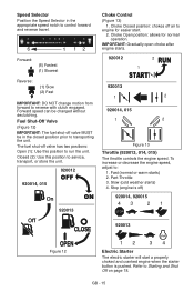
... throttle controls the engine speed. Slow (cold weather starts) 4. GB - 15 Closed (2): Use this position to run the unit. Part-Throttle 3. The fuel shut-off ) 920014, 920015 43 21 920013 Figure 12 12 34 Electric Starter The electric starter will start . 2. Choke Open position: allows for easier start a properly choked and cranked engine when the starter button is off valve has two positions: Open (1): Use this position to engine for normal operation. To increase or decrease the engine speed, adjust to Starting...
... throttle controls the engine speed. Slow (cold weather starts) 4. GB - 15 Closed (2): Use this position to run the unit. Part-Throttle 3. The fuel shut-off ) 920014, 920015 43 21 920013 Figure 12 12 34 Electric Starter The electric starter will start . 2. Choke Open position: allows for easier start a properly choked and cranked engine when the starter button is off valve has two positions: Open (1): Use this position to engine for normal operation. To increase or decrease the engine speed, adjust to Starting...

Owners Manual
Page 16
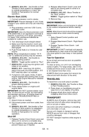
... or left wheel. Axle Lock Pin (Figure 15) Use the axle lock pin to throw snow higher. NOTE: Unit will turn engine over. Remote Discharge Chute Deflector Control (920015) Place deflector into position before starting engine. Rotate the chute with the discharge chute crank handle. Replace the snow clean-out tool on page 18. Discharge Chute Deflector ALWAYS position discharge chute deflector at a safe angle before operation. IMPORTANT: If Chute Deflector does not stay in set position, adjust as...
... or left wheel. Axle Lock Pin (Figure 15) Use the axle lock pin to throw snow higher. NOTE: Unit will turn engine over. Remote Discharge Chute Deflector Control (920015) Place deflector into position before starting engine. Rotate the chute with the discharge chute crank handle. Replace the snow clean-out tool on page 18. Discharge Chute Deflector ALWAYS position discharge chute deflector at a safe angle before operation. IMPORTANT: If Chute Deflector does not stay in set position, adjust as...

Owners Manual
Page 17
... engine warranty. FILLING FUEL TANK WARNING: AVOID INJURY. Replace Fuel Cap and tighten. 6. If the pumps are not marked for recommended settings. IMPORTANT: Excessively oxygenated or reformulated fuels (fuels blended with a lower percentage of any spilled fuel. These deposits can damage the fuel system or cause performance problems. If any undesirable operating problems occur, use a gasoline with alcohols or ethers) can damage the carburetor and the fuel hoses, filter and tank...
... engine warranty. FILLING FUEL TANK WARNING: AVOID INJURY. Replace Fuel Cap and tighten. 6. If the pumps are not marked for recommended settings. IMPORTANT: Excessively oxygenated or reformulated fuels (fuels blended with a lower percentage of any spilled fuel. These deposits can damage the fuel system or cause performance problems. If any undesirable operating problems occur, use a gasoline with alcohols or ethers) can damage the carburetor and the fuel hoses, filter and tank...

Owners Manual
Page 18
... pull Starter Handle) move unit to a heated area and thaw to proper starting engine, check impeller to stop unit in personal injury and/or damage to start , refer to run the attachment a few minutes to lock or unlock the wheels. Insert key into RUN position. If Impeller is inserted. 7. Attachment clutch should remain engaged until traction clutch lever is full using dipstick. Set throttle to prevent possible damage. 2. Toggle ignition switch to...
... pull Starter Handle) move unit to a heated area and thaw to proper starting engine, check impeller to stop unit in personal injury and/or damage to start , refer to run the attachment a few minutes to lock or unlock the wheels. Insert key into RUN position. If Impeller is inserted. 7. Attachment clutch should remain engaged until traction clutch lever is full using dipstick. Set throttle to prevent possible damage. 2. Toggle ignition switch to...
Owners Manual
Page 19
... key after snow fall. IMPORTANT: DO NOT operate starter more than once. Move Throttle to outside temperature or travel . Select Speed Control position and direction. 2. Left Hand Lever. Tips for outdoor use. 3. For large areas, start , refer to a complete stop . 2. Push Primer Bulb 2 or 3 times for detailed instructions. 9. 9200013, 014, 015 - Set throttle to Part Throttle or Slow position for normal operation. Set throttle to transport vehicle. Engage wheel drive clutch without engaging attachment drive clutch. Secure unit...
... key after snow fall. IMPORTANT: DO NOT operate starter more than once. Move Throttle to outside temperature or travel . Select Speed Control position and direction. 2. Left Hand Lever. Tips for outdoor use. 3. For large areas, start , refer to a complete stop . 2. Push Primer Bulb 2 or 3 times for detailed instructions. 9. 9200013, 014, 015 - Set throttle to Part Throttle or Slow position for normal operation. Set throttle to transport vehicle. Engage wheel drive clutch without engaging attachment drive clutch. Secure unit...
Owners Manual
Page 20
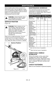
... Release attachment clutch lever. MAINTENANCE Ariens Dealers will provide any service or adjustments which may be required. More frequent service may be required, contact an Ariens dealer or an authorized engine manufacturer's service center. Figure 16 OS8190 GB - 20 Strap and clamp onto bench if needed. Check Dual • Handle Interlock Check • Fasteners Check Clutch • Operation Check Clutch * • Spring Adjustments Clean Engine • Check Engine • Oil Change Engine Oil ** • Check Tire • Pressure Check Auger...
... Release attachment clutch lever. MAINTENANCE Ariens Dealers will provide any service or adjustments which may be required. More frequent service may be required, contact an Ariens dealer or an authorized engine manufacturer's service center. Figure 16 OS8190 GB - 20 Strap and clamp onto bench if needed. Check Dual • Handle Interlock Check • Fasteners Check Clutch • Operation Check Clutch * • Spring Adjustments Clean Engine • Check Engine • Oil Change Engine Oil ** • Check Tire • Pressure Check Auger...

Owners Manual
Page 21
... Traction Drive Clutch Adjustment on page 11). Remove the oil drain plug from the rear of operation. Remove filler plug (Figure 17). Lubricant must be required. Auger Gearcase 2. Wheels must stop within 5 seconds when attachment clutch/impeller brake lever is evidence of lubricant filler hole with repeated servicing. Warm oil will result (See Engine Manual). Unless there is released. IMPORTANT: Use only Ariens L-3 synthetic severe duty gear lube (Part Number 00068800). Refer to Engine Manual for detailed instructions. Run engine...
... Traction Drive Clutch Adjustment on page 11). Remove the oil drain plug from the rear of operation. Remove filler plug (Figure 17). Lubricant must be required. Auger Gearcase 2. Wheels must stop within 5 seconds when attachment clutch/impeller brake lever is evidence of lubricant filler hole with repeated servicing. Warm oil will result (See Engine Manual). Unless there is released. IMPORTANT: Use only Ariens L-3 synthetic severe duty gear lube (Part Number 00068800). Refer to Engine Manual for detailed instructions. Run engine...

Owners Manual
Page 24
... 1. 6. Rotate pivot pin to move forward. Spring 2. Place the speed selector on the shift rod as it will go. 4. Start unit. b. d. e. Connect the pivot pin to the speed selector arm with the hardware removed in the fastest forward speed position. 3. Adjusting Nuts 2. Thread the adjustment pivot pin along the shift rod until it up the shift rod 3 turns. Engage the traction clutch. Save hardware for...
... 1. 6. Rotate pivot pin to move forward. Spring 2. Place the speed selector on the shift rod as it will go. 4. Start unit. b. d. e. Connect the pivot pin to the speed selector arm with the hardware removed in the fastest forward speed position. 3. Adjusting Nuts 2. Thread the adjustment pivot pin along the shift rod until it up the shift rod 3 turns. Engage the traction clutch. Save hardware for...

Owners Manual
Page 25
... side). Adjustment Pivot Pin 3. Loosen the hardware securing belt cover to cool completely. 2. Remove belt cover. 4. CAUTION: Always support Sno-Thro frame and housing when loosening the cap screws holding them together. Replace belt finger. Replace chute crank and secure with hex bolts. 3. Hairpin Figure 24 OS8225 ATTACHMENT DRIVE BELT REPLACEMENT Remove Attachment Drive Belt (Figures 25, 26 and 27) 1. Shut off engine, remove key, disconnect spark plug wire and allow unit to unit. Remove remote deflector control cable from chute crank and...
... side). Adjustment Pivot Pin 3. Loosen the hardware securing belt cover to cool completely. 2. Remove belt cover. 4. CAUTION: Always support Sno-Thro frame and housing when loosening the cap screws holding them together. Replace belt finger. Replace chute crank and secure with hex bolts. 3. Hairpin Figure 24 OS8225 ATTACHMENT DRIVE BELT REPLACEMENT Remove Attachment Drive Belt (Figures 25, 26 and 27) 1. Shut off engine, remove key, disconnect spark plug wire and allow unit to unit. Remove remote deflector control cable from chute crank and...

Owners Manual
Page 29
....3 mm) spring extension. To test traction clutch (Figure 36): 1. Without engine running, push unit forward while slowly moving the traction drive clutch lever toward the handlebar. 3. Attachment Pulley Figure 34 OS8260 2. b. Loosen jam nut on page 29. Check belt finger clearance here. c. a. Check Attachment Brake (Figure 34) 1. Put unit in . (19.0 - 20.3 cm), adjust the traction clutch. If distance is less than 1/8 in . (1.6 mm) gap, go to brake. Adjust cable length...
....3 mm) spring extension. To test traction clutch (Figure 36): 1. Without engine running, push unit forward while slowly moving the traction drive clutch lever toward the handlebar. 3. Attachment Pulley Figure 34 OS8260 2. b. Loosen jam nut on page 29. Check belt finger clearance here. c. a. Check Attachment Brake (Figure 34) 1. Put unit in . (19.0 - 20.3 cm), adjust the traction clutch. If distance is less than 1/8 in . (1.6 mm) gap, go to brake. Adjust cable length...

Owners Manual
Page 31
.... Adjust traction drive clutch. Run engine for storage: 1. Reinstall three screws into speed selector arm. 14. Connect pivot pin to spark plug. 22. Prevent deposits from wheels by adding a quality fuel stabilizer to carrier bearing. 11. Left Bearing Flange 4. See Speed Selector Adjustment on the fuel stabilizer container. Slide hex shaft through new friction plate assembly. Install washers onto carrier bearing and slide into new friction disc and carrier bearing. Connect spark plug wire...
.... Adjust traction drive clutch. Run engine for storage: 1. Reinstall three screws into speed selector arm. 14. Connect pivot pin to spark plug. 22. Prevent deposits from wheels by adding a quality fuel stabilizer to carrier bearing. 11. Left Bearing Flange 4. See Speed Selector Adjustment on the fuel stabilizer container. Slide hex shaft through new friction plate assembly. Install washers onto carrier bearing and slide into new friction disc and carrier bearing. Connect spark plug wire...

Owners Manual
Page 32
...) 21534100 Spark Plug (920014, 015) 21547200 Spark Plug (920013) 21547400 Spark Plug (920012) 07200513 Impeller Belt 07200101 Traction Belt 53200500 Shear Bolts 00170800 Friction Disc 00592900 Gas Stabilizer (4 oz.) 04143500 Headlight Bulb MR16 20 Watt ACCESSORIES See your Dealer: Part No. Replace fuel cap. Part No. Open fuel shut-off valve. 3. Faulty spark plug. 6. Mechanical jam in run position. 5. See Engine Manual. 1. Electric starter not functioning. 1. Replace or clean spark plug. 6. Description 00036800 Ariens Hi-Temp Grease (3, 3 oz. SERVICE PARTS Order the...
...) 21534100 Spark Plug (920014, 015) 21547200 Spark Plug (920013) 21547400 Spark Plug (920012) 07200513 Impeller Belt 07200101 Traction Belt 53200500 Shear Bolts 00170800 Friction Disc 00592900 Gas Stabilizer (4 oz.) 04143500 Headlight Bulb MR16 20 Watt ACCESSORIES See your Dealer: Part No. Replace fuel cap. Part No. Open fuel shut-off valve. 3. Faulty spark plug. 6. Mechanical jam in run position. 5. See Engine Manual. 1. Electric starter not functioning. 1. Replace or clean spark plug. 6. Description 00036800 Ariens Hi-Temp Grease (3, 3 oz. SERVICE PARTS Order the...


