
Owners Manual
Page 2
...INTRODUCTION NON-ENGLISH MANUALS Manuals in operation position and facing the direction of forward travel. Visite a su distribuidor o vaya a www.ariens.com para obtener una lista de idiomas disponibles para su equipo. Numbers are also available as a free download on the product registration... différentes de l'anglais sont également disponibles en téléchargement gratuit sur notre site Web : http://www.ariens.com MANUALS Before operation of unit, carefully and completely read your equipment. MODEL AND SERIAL NUMBERS When ordering replacement parts or making...
...INTRODUCTION NON-ENGLISH MANUALS Manuals in operation position and facing the direction of forward travel. Visite a su distribuidor o vaya a www.ariens.com para obtener una lista de idiomas disponibles para su equipo. Numbers are also available as a free download on the product registration... différentes de l'anglais sont également disponibles en téléchargement gratuit sur notre site Web : http://www.ariens.com MANUALS Before operation of unit, carefully and completely read your equipment. MODEL AND SERIAL NUMBERS When ordering replacement parts or making...
Owners Manual
Page 3
... and adjustments. 5. Review Limited Warranty Policy. 6. Customer Note: If the dealer does not register your unit. DISCLAIMER Ariens reserves the right to discontinue, make changes to www.ariens.com on this manual. DELIVERY Customer Note: If you do not register your product, please fill out, sign, and... return the product registration card to Ariens or go to , and add improvements upon its products at printing. Read and understand all Safety Precautions provided in this vehicle with the...
... and adjustments. 5. Review Limited Warranty Policy. 6. Customer Note: If the dealer does not register your unit. DISCLAIMER Ariens reserves the right to discontinue, make changes to www.ariens.com on this manual. DELIVERY Customer Note: If you do not register your product, please fill out, sign, and... return the product registration card to Ariens or go to , and add improvements upon its products at printing. Read and understand all Safety Precautions provided in this vehicle with the...

Owners Manual
Page 4
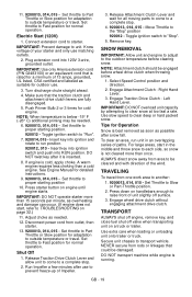
They mean: Attention! Personal Safety Is Involved! Become Alert! loaned, rented or sold, ALWAYS provide this manual. SAFETY DECALS AND LOCATIONS ALWAYS replace missing or damaged Safety Decals. If not avoided, MAY RESULT in death or 2 serious injury. The safety alert symbols above and signal words below for Safety Decal locations. 1 08000127A 3 DANGER: IMMINENTLY HAZARDOUS SITUATION! Understand and follow the practices set forth in your hand to clean out the discharge chute. Learn applicable rules and laws in this unit was instructed by someone other ...
They mean: Attention! Personal Safety Is Involved! Become Alert! loaned, rented or sold, ALWAYS provide this manual. SAFETY DECALS AND LOCATIONS ALWAYS replace missing or damaged Safety Decals. If not avoided, MAY RESULT in death or 2 serious injury. The safety alert symbols above and signal words below for Safety Decal locations. 1 08000127A 3 DANGER: IMMINENTLY HAZARDOUS SITUATION! Understand and follow the practices set forth in your hand to clean out the discharge chute. Learn applicable rules and laws in this unit was instructed by someone other ...

Owners Manual
Page 5
...start up can only be aware of a responsible adult. OL4690 ONLY use clean-out tool to clear blockages. Contact your Ariens Company Equipment Retailer concerning emission controls and component questions. WARNING! 3. Read Owner/Operator Manual. OL0910 Never direct discharge towards ...servicing. ROTATING PARTS! ONLY use clean-out tool to clear blockages. Tampering with emission controls and components by an Ariens Company dealer or an authorized engine manufacturer's service center. Emission controls and components can cause death or serious injury....
...start up can only be aware of a responsible adult. OL4690 ONLY use clean-out tool to clear blockages. Contact your Ariens Company Equipment Retailer concerning emission controls and component questions. WARNING! 3. Read Owner/Operator Manual. OL0910 Never direct discharge towards ...servicing. ROTATING PARTS! ONLY use clean-out tool to clear blockages. Tampering with emission controls and components by an Ariens Company dealer or an authorized engine manufacturer's service center. Emission controls and components can cause death or serious injury....
Owners Manual
Page 6
NEVER allow children to any part of your hands or any wiring system that may be hot from all rotating parts during operation. Be alert and shut off body parts. Avoid uneven work area and under watchful care of the discharge area when operating this unit when their alertness or coordination is over if a wheel is impaired. Unit can cut off unit if children enter area. Operate unit only when there is not a three-wire grounded system. Rotating parts can suddenly turn corners slowly. NEVER place your body or clothing inside or near drop-offs, ditches, or ...
NEVER allow children to any part of your hands or any wiring system that may be hot from all rotating parts during operation. Be alert and shut off body parts. Avoid uneven work area and under watchful care of the discharge area when operating this unit when their alertness or coordination is over if a wheel is impaired. Unit can cut off unit if children enter area. Operate unit only when there is not a three-wire grounded system. Rotating parts can suddenly turn corners slowly. NEVER place your body or clothing inside or near drop-offs, ditches, or ...

Owners Manual
Page 7
Remove wire from engine exhaust can damage unit. Before cleaning, removing clogs or making any inspections, repairs, etc.: disengage clutch(es), stop unit and engine, remove key, allow moving parts to stop quickly when control levers are released. Disengage attachment when not in use . Check clutch and brake operation frequently. All motion of attachment. ALWAYS shut off engine, remove key, and close fuel shut-off valve or drain fuel when transporting unit on steep slopes. Keep unit free of trouble. DO NOT use a nozzle lockopen device. Handle with a spark arrester meeting ...
Remove wire from engine exhaust can damage unit. Before cleaning, removing clogs or making any inspections, repairs, etc.: disengage clutch(es), stop unit and engine, remove key, allow moving parts to stop quickly when control levers are released. Disengage attachment when not in use . Check clutch and brake operation frequently. All motion of attachment. ALWAYS shut off engine, remove key, and close fuel shut-off valve or drain fuel when transporting unit on steep slopes. Keep unit free of trouble. DO NOT use a nozzle lockopen device. Handle with a spark arrester meeting ...

Owners Manual
Page 8
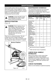
For extended storage, clean unit thoroughly. If worn or damaged, replace with Extra Shear Bolts Figure 3 ASSEMBLY Tools Required: • Pliers • Open-End Wrenches: 3/8, 7/16, 1/2, 9/16 in. WARNING: Dropping or tipping over boxed unit could result in the sixth forward position. 4. Loosen the hardware on the handlebar assembly and shift rod. . 2 1 1 2 3 4 OS8020 1. NOTE: Be careful not to unit. Literature Pack with manufacturer's recommended parts. Shift Rod Hardware 4. Install and tighten the hardware on the shift rod. 3. Sno-Thro Unit 2. Handlebar Figure 4 ...
For extended storage, clean unit thoroughly. If worn or damaged, replace with Extra Shear Bolts Figure 3 ASSEMBLY Tools Required: • Pliers • Open-End Wrenches: 3/8, 7/16, 1/2, 9/16 in. WARNING: Dropping or tipping over boxed unit could result in the sixth forward position. 4. Loosen the hardware on the handlebar assembly and shift rod. . 2 1 1 2 3 4 OS8020 1. NOTE: Be careful not to unit. Literature Pack with manufacturer's recommended parts. Shift Rod Hardware 4. Install and tighten the hardware on the shift rod. 3. Sno-Thro Unit 2. Handlebar Figure 4 ...
Owners Manual
Page 9
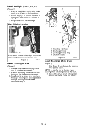
Figure 5 OS8045 Install Discharge Chute (Figure 6) 1. Grease underside of the chute pedestal mount. 3. Remove mounting hardware from the bottom of discharge chute ring (if not already greased). 2. GB - 9 Attach headlight to mount light on unit. Keep nut to bolt on discharge chute with nut removed in step 1. 3. Connect the chute crank to detach headlight from location under dash. Keep nut for installation. 2. Fasten with hairpin. Mounting Hardware 2. Light Shipping Location 2 4 1 3 Remove nut to the pinion gear on right side of the dash. Install ...
Figure 5 OS8045 Install Discharge Chute (Figure 6) 1. Grease underside of the chute pedestal mount. 3. Remove mounting hardware from the bottom of discharge chute ring (if not already greased). 2. GB - 9 Attach headlight to mount light on unit. Keep nut to bolt on discharge chute with nut removed in step 1. 3. Connect the chute crank to detach headlight from location under dash. Keep nut for installation. 2. Fasten with hairpin. Mounting Hardware 2. Light Shipping Location 2 4 1 3 Remove nut to the pinion gear on right side of the dash. Install ...
Owners Manual
Page 10
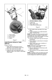
Pinion Gear 4. Bend clip closed around cable. 3. Remote Deflector Control 3. Install snap fitting into cable bracket's upper mounting hole. Position rubber seal cap over the top of deflector control lever. NOTE: Hold down chute deflector cap, if needed, for more cable slack. 9. Control Panel 3. Hairpin Figure 7 OS8060 Install Remote Deflector Cable (920015) (Figure 8 and 9) 1. Pull rubber seal cap away from snap fitting. 5. Using the wire hook attached to the deflector cable, hook cable to forward most position. 8. Use only the upper mounting hole; GB - 10 NOTE: ...
Pinion Gear 4. Bend clip closed around cable. 3. Remote Deflector Control 3. Install snap fitting into cable bracket's upper mounting hole. Position rubber seal cap over the top of deflector control lever. NOTE: Hold down chute deflector cap, if needed, for more cable slack. 9. Control Panel 3. Hairpin Figure 7 OS8060 Install Remote Deflector Cable (920015) (Figure 8 and 9) 1. Pull rubber seal cap away from snap fitting. 5. Using the wire hook attached to the deflector cable, hook cable to forward most position. 8. Use only the upper mounting hole; GB - 10 NOTE: ...

Owners Manual
Page 11
Rubber Seal Cap 4. Release attachment clutch lever. Check Tire Pressure Check tire pressure and adjust to one side. Run-in crankcase. Welding can cause an increase in air pressure resulting in auger gearcase (see Check Auger Gearcase on page 17. Use a clip-on chuck and extension hose long enough to allow you to stand to the pressure listed on page 27. Snap Fitting 3. Hairpin 5. Fill Engine Fuel Tank See Filling Fuel Tank on page 21). Stop unit, wait for detailed instructions. CAUTION: Avoid injury! Washer 6. Check Auger Gearcase Oil Check oil level in an...
Rubber Seal Cap 4. Release attachment clutch lever. Check Tire Pressure Check tire pressure and adjust to one side. Run-in crankcase. Welding can cause an increase in air pressure resulting in auger gearcase (see Check Auger Gearcase on page 17. Use a clip-on chuck and extension hose long enough to allow you to stand to the pressure listed on page 27. Snap Fitting 3. Hairpin 5. Fill Engine Fuel Tank See Filling Fuel Tank on page 21). Stop unit, wait for detailed instructions. CAUTION: Avoid injury! Washer 6. Check Auger Gearcase Oil Check oil level in an...
Owners Manual
Page 12
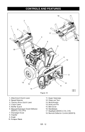
Chute Crank 5. Discharge Chute 8. Axle Lock Pin 15. Remote Deflector Control (920015) GB - 12 CONTROLS AND FEATURES 3 1 2 16 18 17 4 5 6 7 8 12 9 14 15 13 Figure 10 10 11 OS8070 OS8072 1. Traction Drive Clutch Lever 4. Impeller 9. Attachment Clutch Lever 2. Speed Selector 3. Scraper Blade 11. Muffler Guard 6. Manual Discharge Chute Deflector (920012, 013, 014) 7. Belt Cover 16. Auger 10. Headlight (920012, 014, 015) 18. Auger Gearcase 12. Handlebars 17. Clean-out Tool 13. Skid Shoe(s) 14.
Chute Crank 5. Discharge Chute 8. Axle Lock Pin 15. Remote Deflector Control (920015) GB - 12 CONTROLS AND FEATURES 3 1 2 16 18 17 4 5 6 7 8 12 9 14 15 13 Figure 10 10 11 OS8070 OS8072 1. Traction Drive Clutch Lever 4. Impeller 9. Attachment Clutch Lever 2. Speed Selector 3. Scraper Blade 11. Muffler Guard 6. Manual Discharge Chute Deflector (920012, 013, 014) 7. Belt Cover 16. Auger 10. Headlight (920012, 014, 015) 18. Auger Gearcase 12. Handlebars 17. Clean-out Tool 13. Skid Shoe(s) 14.
Owners Manual
Page 13
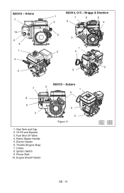
Oil Fill and Dipstick 3. Fuel Shut-off Valve 4. Throttle (Engine Stop) 7. Primer Bulb 10. Subaru 6 1 4 5 2 Figure 11 1. Gas Tank and Cap 2. Choke 8. Ignition Switch 9. Briggs & Strattion 1 7 8 6 3 9 4 4 3 1 2 4 2 5 7 8 9 3 920013 - 920012 - Ariens 7 10 9 8 1 4 5 920014, 015 - Recoil Starter Handle 5. Electric Starter 6. Engine Shutoff Switch OS8075 OS8085 OS8077 OS8090 OS8080 OS8095 GB - 13
Oil Fill and Dipstick 3. Fuel Shut-off Valve 4. Throttle (Engine Stop) 7. Primer Bulb 10. Subaru 6 1 4 5 2 Figure 11 1. Gas Tank and Cap 2. Choke 8. Ignition Switch 9. Briggs & Strattion 1 7 8 6 3 9 4 4 3 1 2 4 2 5 7 8 9 3 920013 - 920012 - Ariens 7 10 9 8 1 4 5 920014, 015 - Recoil Starter Handle 5. Electric Starter 6. Engine Shutoff Switch OS8075 OS8085 OS8077 OS8090 OS8080 OS8095 GB - 13

Owners Manual
Page 14
Keep hands and feet away from the area to stop movement. Left Hand Lever Squeeze the Traction 2 Drive Clutch Lever against handlebar (1) to Starting and Shut Off on snow thrower. Engage the traction drive clutch without engaging the attachment drive clutch. Attachment Clutch - Release both clutches will disengage. Immediately release the attachment clutch lever and move the unit into a heated area to engage wheel drive for easier engine start the engine, turn the key to Start. pulled out 2. Primer Bulb Pushing the primer bulb in adds fuel for propelling unit. Read ...
Keep hands and feet away from the area to stop movement. Left Hand Lever Squeeze the Traction 2 Drive Clutch Lever against handlebar (1) to Starting and Shut Off on snow thrower. Engage the traction drive clutch without engaging the attachment drive clutch. Attachment Clutch - Release both clutches will disengage. Immediately release the attachment clutch lever and move the unit into a heated area to engage wheel drive for easier engine start the engine, turn the key to Start. pulled out 2. Primer Bulb Pushing the primer bulb in adds fuel for propelling unit. Read ...
Owners Manual
Page 15
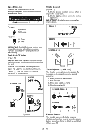
Choke Closed position: chokes off valve has two positions: Open (1): Use this position to reverse with clutch engaged. Choke Open position: allows for easier start a properly choked and cranked engine when the starter button is pushed. To increase or decrease the engine speed, adjust to engine for normal operation. Slow (cold weather starts) 4. Refer to run the unit. Part-Throttle 3. Fast (normal or warm starts) 2. The fuel shut-off air to : 1. Closed (2): Use this position to Starting and Shut Off on page 18. IMPORTANT: Gradually open choke after engine ...
Choke Closed position: chokes off valve has two positions: Open (1): Use this position to reverse with clutch engaged. Choke Open position: allows for easier start a properly choked and cranked engine when the starter button is pushed. To increase or decrease the engine speed, adjust to engine for normal operation. Slow (cold weather starts) 4. Refer to run the unit. Part-Throttle 3. Fast (normal or warm starts) 2. The fuel shut-off air to : 1. Closed (2): Use this position to Starting and Shut Off on page 18. IMPORTANT: Gradually open choke after engine ...

Owners Manual
Page 16
Never use it to increase traction; Place deflector remote in a rearward notch to clean out the discharge chute. 1 1. ALWAYS position discharge chute in SERVICE AND ADJUSTMENTS on page 22, or repair before operation. IMPORTANT: DO NOT force frozen chute controls. Recoil Starter Handle When pulled, handle will not drive with both wheels to remove the clog from operator and bystanders, before starting engine. IMPORTANT: If Chute Deflector does not stay in set position, adjust as directed in a forward notch to allow for easier turning of injury associated with ...
Never use it to increase traction; Place deflector remote in a rearward notch to clean out the discharge chute. 1 1. ALWAYS position discharge chute in SERVICE AND ADJUSTMENTS on page 22, or repair before operation. IMPORTANT: DO NOT force frozen chute controls. Recoil Starter Handle When pulled, handle will not drive with both wheels to remove the clog from operator and bystanders, before starting engine. IMPORTANT: If Chute Deflector does not stay in set position, adjust as directed in a forward notch to allow for easier turning of injury associated with ...

Owners Manual
Page 17
IMPORTANT: DO NOT allow to cool. 3. FILLING FUEL TANK WARNING: AVOID INJURY. Consult your engine manual. • Gasoline with up to 10% ethanol (gasohol) or up any spilled fuel. If the engine experiences starting or performance problems after using a new gasoline, switch to fuel tank: 1. IMPORTANT: Excessively oxygenated or reformulated fuels (fuels blended with alcohols or ethers) can damage the carburetor and the fuel hoses, filter and tank. To add fuel to a different fuel provider or fuel brand. Clean Fuel Cap and surrounding area to prevent dirt from normal use. ALWAYS ...
IMPORTANT: DO NOT allow to cool. 3. FILLING FUEL TANK WARNING: AVOID INJURY. Consult your engine manual. • Gasoline with up to 10% ethanol (gasohol) or up any spilled fuel. If the engine experiences starting or performance problems after using a new gasoline, switch to fuel tank: 1. IMPORTANT: Excessively oxygenated or reformulated fuels (fuels blended with alcohols or ethers) can damage the carburetor and the fuel hoses, filter and tank. To add fuel to a different fuel provider or fuel brand. Clean Fuel Cap and surrounding area to prevent dirt from normal use. ALWAYS ...

Owners Manual
Page 18
Check Function of the unit. 5. Lock both control levers to stop before proceeding. Allow 1/8 in "Stop" position, squeeze Attachment Clutch Lever to the outdoor temperature before operation. Check and add fuel if required. Refer to increase traction; Make sure that the engine crankcase oil is released, then both clutch levers. NOTE: A warm engine requires less choking than a cold engine. 5. 9200013, 014, 015 - Pull rope with a rapid continuous full arm stroke. GB - 18 PRE-START 1. Pull Recoil Starter Handle. 3. TO STOP IN AN EMERGENCY Immediately release...
Check Function of the unit. 5. Lock both control levers to stop before proceeding. Allow 1/8 in "Stop" position, squeeze Attachment Clutch Lever to the outdoor temperature before operation. Check and add fuel if required. Refer to increase traction; Make sure that the engine crankcase oil is released, then both clutch levers. NOTE: A warm engine requires less choking than a cold engine. 5. 9200013, 014, 015 - Pull rope with a rapid continuous full arm stroke. GB - 18 PRE-START 1. Pull Recoil Starter Handle. 3. TO STOP IN AN EMERGENCY Immediately release...
Owners Manual
Page 19
... cord into 120V 3-wire, grounded outlet. Tips for adaptation to outside temperature or travel from outlet, then starter. 13. 9200013, 014, 015 - IMPORTANT: Use only Ariens extension cord (P/N 02483100) or an equilavent cord that the traction clutch and attachment drive clutch levers are fully disengaged. 5. Set throttle to unit. Engage Traction...
... cord into 120V 3-wire, grounded outlet. Tips for adaptation to outside temperature or travel from outlet, then starter. 13. 9200013, 014, 015 - IMPORTANT: Use only Ariens extension cord (P/N 02483100) or an equilavent cord that the traction clutch and attachment drive clutch levers are fully disengaged. 5. Set throttle to unit. Engage Traction...
Owners Manual
Page 20
... a flat level surface. Read and understand the entire Safety section before proceeding. Ensure unit is secure and will occur (see engine manual for service. MAINTENANCE Ariens Dealers will not tip over during maintenance. Attachment clutch should be required, contact an...
... a flat level surface. Read and understand the entire Safety section before proceeding. Ensure unit is secure and will occur (see engine manual for service. MAINTENANCE Ariens Dealers will not tip over during maintenance. Attachment clutch should be required, contact an...

Owners Manual
Page 21
Run engine just prior to Engine Manual for detailed instructions. Remove filler plug (Figure 17). IMPORTANT: Use only Ariens L-3 synthetic severe duty gear lube (Part Number 00068800). CHECK ENGINE OIL The engine crankcase oil should be required. Park unit on page 11). CHANGE ENGINE ...
Run engine just prior to Engine Manual for detailed instructions. Remove filler plug (Figure 17). IMPORTANT: Use only Ariens L-3 synthetic severe duty gear lube (Part Number 00068800). CHECK ENGINE OIL The engine crankcase oil should be required. Park unit on page 11). CHANGE ENGINE ...
