
Owners Manual
Page 1
Compact 24 LET (SN 000101 +) E10 The use of any gasoline exceeding 10% ethanol (E10) or 10% MTBE will void the product warranty. 920 Series Sno-Thro® Owner/Operator Manual Manuel Du Propriétaire/Utilisateur Models 920013 - Compact 22 LE (SN 123000 +) 920014 - Compact 24 LE (SN 000101 +) 920022 - Compact 24 LE (SN 123000 +) 920021 - ENGLISH FRANÇAIS 04631900 4/13 Printed in USA L'utilisation d'une essence contenant plus de 10% d'éthanol (E10) ou de 10% de MTBE annulent la garantie.
Compact 24 LET (SN 000101 +) E10 The use of any gasoline exceeding 10% ethanol (E10) or 10% MTBE will void the product warranty. 920 Series Sno-Thro® Owner/Operator Manual Manuel Du Propriétaire/Utilisateur Models 920013 - Compact 22 LE (SN 123000 +) 920014 - Compact 24 LE (SN 000101 +) 920022 - Compact 24 LE (SN 123000 +) 920021 - ENGLISH FRANÇAIS 04631900 4/13 Printed in USA L'utilisation d'une essence contenant plus de 10% d'éthanol (E10) ou de 10% de MTBE annulent la garantie.
Owners Manual
Page 2
... langues différentes de l'anglais sont également disponibles en téléchargement gratuit sur notre site Web : http://www.ariens.com MANUALS Before operation of your manuals. ENGINE MANUAL The engine on the frame of languages available for a replacement manual. If the...serial number label, located on this unit is not available, contact the engine manufacturer for your unit (Figure 1). Visit your dealer or www.ariens.com for a list of your equipment. Refer to left, right, front, or rear are given from your unit during normal operation and ...
... langues différentes de l'anglais sont également disponibles en téléchargement gratuit sur notre site Web : http://www.ariens.com MANUALS Before operation of your manuals. ENGINE MANUAL The engine on the frame of languages available for a replacement manual. If the...serial number label, located on this unit is not available, contact the engine manufacturer for your unit (Figure 1). Visit your dealer or www.ariens.com for a list of your equipment. Refer to left, right, front, or rear are given from your unit during normal operation and ...

Owners Manual
Page 3
... personal injury or death arising out of the use of purchase if you have difficulty following the instructions, contact your nearest Ariens Dealer for any time without complete assembly and instruction by your retailer, it is returned. NOTICE: To locate your unit. ... operation of this product without public notice or obligation. Customer Note: If the dealer does not register your responsibility to www.ariens.com. Ariens disclaims liability for assistance. Review Limited Warranty Policy. 6. Do not operate the Sno-Thro unless all assembly instructions in this ...
... personal injury or death arising out of the use of purchase if you have difficulty following the instructions, contact your nearest Ariens Dealer for any time without complete assembly and instruction by your retailer, it is returned. NOTICE: To locate your unit. ... operation of this product without public notice or obligation. Customer Note: If the dealer does not register your responsibility to www.ariens.com. Ariens disclaims liability for assistance. Review Limited Warranty Policy. 6. Do not operate the Sno-Thro unless all assembly instructions in this ...

Owners Manual
Page 4
SAFETY ALERTS Look for these symbols to figure below are used on safe and proper operation. Personal Safety Is Involved! Obey The Message! DANGER: IMMINENTLY HAZARDOUS SITUATION! If not avoided, WILL RESULT in this manual. Understand and follow the practices set forth in death or 2 serious injury. REQUIRED OPERATOR TRAINING Original purchaser of injury associated with the rotating impeller is to be used by the seller on decals and in death or serious injury. Refer to point out important safety precautions. Read and understand all safety messages. SAFETY ...
SAFETY ALERTS Look for these symbols to figure below are used on safe and proper operation. Personal Safety Is Involved! Obey The Message! DANGER: IMMINENTLY HAZARDOUS SITUATION! If not avoided, WILL RESULT in this manual. Understand and follow the practices set forth in death or 2 serious injury. REQUIRED OPERATOR TRAINING Original purchaser of injury associated with the rotating impeller is to be used by the seller on decals and in death or serious injury. Refer to point out important safety precautions. Read and understand all safety messages. SAFETY ...

Owners Manual
Page 5
Danger! NEVER use your hands. Keep people away from unit while operating. ONLY use clean-out tool to clear blockages. DANGER! Wear appropriate hearing protection. NEVER use your hands or feet. Danger! DANGER! Never direct discharge towards persons or property that may be injured or damaged by thrown objects. ROTATING PARTS! Read Owner/Operator Manual. High speed impeller rotates below discharge opening. Wait for any reason. • Keep all moving parts to stop before making any repairs or adjustments. Keep clear of a responsible adult. ROTATING...
Danger! NEVER use your hands. Keep people away from unit while operating. ONLY use clean-out tool to clear blockages. DANGER! Wear appropriate hearing protection. NEVER use your hands or feet. Danger! DANGER! Never direct discharge towards persons or property that may be injured or damaged by thrown objects. ROTATING PARTS! Read Owner/Operator Manual. High speed impeller rotates below discharge opening. Wait for any reason. • Keep all moving parts to stop before making any repairs or adjustments. Keep clear of a responsible adult. ROTATING...

Owners Manual
Page 6
Emission controls and components can cause injury or death. Unintentional engine start up can cause injury. ALWAYS be adjusted by an Ariens Company dealer or an authorized engine manufacturer's service center. Keep children and people away. Be alert and shut off fingers or a hand. DO ... key and/or wire from engine exhaust can only be aware of traffic when operating along streets or curbs. Keep children out of your Ariens Company Equipment Retailer concerning emission controls and component questions. Only trained adults may operate unit. Keep area of operation clear of unit and work...
Emission controls and components can cause injury or death. Unintentional engine start up can cause injury. ALWAYS be adjusted by an Ariens Company dealer or an authorized engine manufacturer's service center. Keep children and people away. Be alert and shut off fingers or a hand. DO ... key and/or wire from engine exhaust can only be aware of traffic when operating along streets or curbs. Keep children out of your Ariens Company Equipment Retailer concerning emission controls and component questions. Only trained adults may operate unit. Keep area of operation clear of unit and work...

Owners Manual
Page 7
Immediately stop . Allow hot parts to clear gravel or crushed rock surfaces safely. Disengage all movement on slopes slow and gradual. Adjust skid shoes to cool. ALWAYS shut off valve or drain fuel when transporting unit on the ground away from the truck or trailer and refuel it will occur. Keep all clutches before starting or stopping on a slope unless absolutely necessary. Keep unit free of slopes. DO NOT use . Fuel is used, must stop . NO smoking, NO sparks, NO flames. Secure unit so it on steep slopes. DO NOT change clothing immediately. Always ...
Immediately stop . Allow hot parts to clear gravel or crushed rock surfaces safely. Disengage all movement on slopes slow and gradual. Adjust skid shoes to cool. ALWAYS shut off valve or drain fuel when transporting unit on the ground away from the truck or trailer and refuel it will occur. Keep all clutches before starting or stopping on a slope unless absolutely necessary. Keep unit free of slopes. DO NOT use . Fuel is used, must stop . NO smoking, NO sparks, NO flames. Secure unit so it on steep slopes. DO NOT change clothing immediately. Always ...

Owners Manual
Page 8
... parts; N/A 1 Discharge Chute Assembly 11. N/A 1 Chute Crank Assembly 12. N/A 1 Literature Pack If any of the contents listed are included as a part of your local Ariens dealer. PACKAGE CONTENTS PACKAGE CONTENTS Check the contents of the Lower Handlebar: 3. 00597451 1 Lower Handlebar 4. 06221600 4 5/16" x 2-1/4" Round Head Square Neck Grade 5 Bolt 5. 07500005 4 Handlebar ...
... parts; N/A 1 Discharge Chute Assembly 11. N/A 1 Chute Crank Assembly 12. N/A 1 Literature Pack If any of the contents listed are included as a part of your local Ariens dealer. PACKAGE CONTENTS PACKAGE CONTENTS Check the contents of the Lower Handlebar: 3. 00597451 1 Lower Handlebar 4. 06221600 4 5/16" x 2-1/4" Round Head Square Neck Grade 5 Bolt 5. 07500005 4 Handlebar ...

Owners Manual
Page 9
Do not remove wheels completely. Wheel 4. Mounting Hole Figure 4 2. Lower Handlebar 3. 5/16" x 2-1/4" Round Head Square Neck Grade 5 Bolt 4. Flat Steel Washer 6. Wheel Pin 3. Secure lower handlebar to unit using two sets of frame (Figure 6). . 3 4 2 1 1. Upper Handlebar Assembly 2. Handlebar Spacer 5. Cable Eyelet 3. Rotate lower handlebar out from unit so lower handlebar mounting holes align with mounting holes on back of the handlebar hardware. Slide both wheels back into place and reinstall wheel pins (Figure 18). 1. Hook spring end of the handlebars (Figure...
Do not remove wheels completely. Wheel 4. Mounting Hole Figure 4 2. Lower Handlebar 3. 5/16" x 2-1/4" Round Head Square Neck Grade 5 Bolt 4. Flat Steel Washer 6. Wheel Pin 3. Secure lower handlebar to unit using two sets of frame (Figure 6). . 3 4 2 1 1. Upper Handlebar Assembly 2. Handlebar Spacer 5. Cable Eyelet 3. Rotate lower handlebar out from unit so lower handlebar mounting holes align with mounting holes on back of the handlebar hardware. Slide both wheels back into place and reinstall wheel pins (Figure 18). 1. Hook spring end of the handlebars (Figure...

Owners Manual
Page 10
Remove packaging around shift rod. 5. Secure the wire harness to the handlebars using one 1/4" x 1-1/2" oval head machine screw and one 1/4" locking washer. Gather excess wire harness length and fasten together with cable tie included in Attachment Clutch/Brake Adjustment on page 30. 8. Install Trigger Cable Assembly (920022) (Figure 9) NOTICE: Trigger cable assembly comes attached to the wire harness. 5. Shift Rod 2. Shift Rod Hardware 4. Lower Handlebar Figure 7 2. Engine Electrical Plug 5. EN - 10 Install the remaining handlebar hardware attaching the upper ...
Remove packaging around shift rod. 5. Secure the wire harness to the handlebars using one 1/4" x 1-1/2" oval head machine screw and one 1/4" locking washer. Gather excess wire harness length and fasten together with cable tie included in Attachment Clutch/Brake Adjustment on page 30. 8. Install Trigger Cable Assembly (920022) (Figure 9) NOTICE: Trigger cable assembly comes attached to the wire harness. 5. Shift Rod 2. Shift Rod Hardware 4. Lower Handlebar Figure 7 2. Engine Electrical Plug 5. EN - 10 Install the remaining handlebar hardware attaching the upper ...

Owners Manual
Page 11
Internal Locking Washer Figure 9 INSTALL DISCHARGE CHUTE AND DISCHARGE CHUTE CRANK (Figures 10 and 11) 1. Finger tighten the mounting hardware removed in the support bracket under control panel. Discharge Chute 3. Orient the chute and pedestal to its most vertical position and tighten pedestal hardware to the control panel. 6. Trigger Cable Assembly 2. Chute Pedestal 5. Replace gear cover on discharge chute with spring clip pin. 7. Oval Head Machine Screw 3. Grease underside of chute pedestal. 5. Slide Chute Crank through the nylon bushing in step 2. ...
Internal Locking Washer Figure 9 INSTALL DISCHARGE CHUTE AND DISCHARGE CHUTE CRANK (Figures 10 and 11) 1. Finger tighten the mounting hardware removed in the support bracket under control panel. Discharge Chute 3. Orient the chute and pedestal to its most vertical position and tighten pedestal hardware to the control panel. 6. Trigger Cable Assembly 2. Chute Pedestal 5. Replace gear cover on discharge chute with spring clip pin. 7. Oval Head Machine Screw 3. Grease underside of chute pedestal. 5. Slide Chute Crank through the nylon bushing in step 2. ...

Owners Manual
Page 12
Spring Clip Pin Figure 11 Install Remote Deflector Cable (920014, 022, 021) (Figures 12 and 13) 1. Rubber Seal Cap 4. Install snap fitting into cable bracket's mounting hole located under the control panel. 3. Move deflector control lever to discharge chute crank. Pinion Gear 4. Snap Fitting 3. Position rubber seal cap over the top of deflector control lever. Pull rubber seal cap away from snap fitting (Figure 12). 2 4 1. EN - 12 Mounting Hole 2. Bushing 6. Attach cable eye to control lever with bushing and hairpin. 7. . 2 1 4 35 1 6 3 1. Support Bracket 3. ...
Spring Clip Pin Figure 11 Install Remote Deflector Cable (920014, 022, 021) (Figures 12 and 13) 1. Rubber Seal Cap 4. Install snap fitting into cable bracket's mounting hole located under the control panel. 3. Move deflector control lever to discharge chute crank. Pinion Gear 4. Snap Fitting 3. Position rubber seal cap over the top of deflector control lever. Pull rubber seal cap away from snap fitting (Figure 12). 2 4 1. EN - 12 Mounting Hole 2. Bushing 6. Attach cable eye to control lever with bushing and hairpin. 7. . 2 1 4 35 1 6 3 1. Support Bracket 3. ...

Owners Manual
Page 13
... Dual Handle Interlock Without the engine running, press down (engage) both clutches must disengage. Release attachment clutch lever. Check Track Tension (920022) Check tracking of travel see Check Auger Gearcase on page 30. 5. Cable Clip 4. Cable Support Bracket 7. Attachment clutch should remain ... tire assembly. Check Tire Pressure (920013, 014, 021) Check tire pressure and adjust to Attachment Clutch/Brake Adjustment on page 24). Check Engine Crankcase Oil IMPORTANT: The engine may be sure deflector works properly. Check Function Of All Controls Ensure unit runs ...
... Dual Handle Interlock Without the engine running, press down (engage) both clutches must disengage. Release attachment clutch lever. Check Track Tension (920022) Check tracking of travel see Check Auger Gearcase on page 30. 5. Cable Clip 4. Cable Support Bracket 7. Attachment clutch should remain ... tire assembly. Check Tire Pressure (920013, 014, 021) Check tire pressure and adjust to Attachment Clutch/Brake Adjustment on page 24). Check Engine Crankcase Oil IMPORTANT: The engine may be sure deflector works properly. Check Function Of All Controls Ensure unit runs ...

Owners Manual
Page 16
Electric Starter 6. Ignition Switch 9. Choke 8. Fuel Shut-off Valve 4. Primer Bulb 10. Recoil Starter Handle 5. Throttle (920014) 7. Oil Drain Plug 11. Engine Shut Off Switch (920013, 021, 022) 8 4 6 10 EN - 16 Ariens 2 1 5 920014 - Gas Tank and Cap 2. 920013, 021, 022 - Briggs & Stratton 1 2 5 4 1 7 4 71 3 9 11 9 8 3 10 Figure 16 1. Oil Fill and Dipstick 3.
Electric Starter 6. Ignition Switch 9. Choke 8. Fuel Shut-off Valve 4. Primer Bulb 10. Recoil Starter Handle 5. Throttle (920014) 7. Oil Drain Plug 11. Engine Shut Off Switch (920013, 021, 022) 8 4 6 10 EN - 16 Ariens 2 1 5 920014 - Gas Tank and Cap 2. 920013, 021, 022 - Briggs & Stratton 1 2 5 4 1 7 4 71 3 9 11 9 8 3 10 Figure 16 1. Oil Fill and Dipstick 3.

Owners Manual
Page 17
Dual Handle Interlock When Attachment Clutch and then Traction Drive Clutch are engaged, the Attachment Clutch will vary according to snow depth and moisture content. pushed in the auger housing. WARNING: To avoid injury to be frozen in NOTICE: DO NOT twist 1 key after it is engaged, the impeller may be cleared, press down ) if released. Keep hands and feet away from the area to hands and feet, always disengage clutches, shut off the surface. Forward 1 speed will remain engaged (lever down on snow thrower. Engage the traction drive clutch without ...
Dual Handle Interlock When Attachment Clutch and then Traction Drive Clutch are engaged, the Attachment Clutch will vary according to snow depth and moisture content. pushed in the auger housing. WARNING: To avoid injury to be frozen in NOTICE: DO NOT twist 1 key after it is engaged, the impeller may be cleared, press down ) if released. Keep hands and feet away from the area to hands and feet, always disengage clutches, shut off the surface. Forward 1 speed will remain engaged (lever down on snow thrower. Engage the traction drive clutch without ...

Owners Manual
Page 18
The fuel shut-off valve MUST be changed without declutching. Choke Open position: allows for easier start a properly choked and cranked engine when the starter button is the most common cause of injury associated with snow throwers. IMPORTANT: Gradually open choke after engine starts. 920013, 021, 022 2 RUN Throttle (920014) The throttle controls the engine speed. Slow 1 2 3 Electric Starter The electric starter will turn engine over. Never use your hand to service, transport, or store the unit. 920014 920013, 021, 022 1 OFF 2 1 ON 2 Choke Control 1. Choke Closed...
The fuel shut-off valve MUST be changed without declutching. Choke Open position: allows for easier start a properly choked and cranked engine when the starter button is the most common cause of injury associated with snow throwers. IMPORTANT: Gradually open choke after engine starts. 920013, 021, 022 2 RUN Throttle (920014) The throttle controls the engine speed. Slow 1 2 3 Electric Starter The electric starter will turn engine over. Never use your hand to service, transport, or store the unit. 920014 920013, 021, 022 1 OFF 2 1 ON 2 Choke Control 1. Choke Closed...

Owners Manual
Page 19
... in a rearward notch to throw snow lower. NOTICE: Unit will not drive with the discharge chute crank handle. Axle Lock Pin Figure 18 Track Angle (920022) The track angle can be adjusted to lock or unlock the right or left wheel. Release the trigger to increase traction; Discharge Chute Discharge chute rotates...
... in a rearward notch to throw snow lower. NOTICE: Unit will not drive with the discharge chute crank handle. Axle Lock Pin Figure 18 Track Angle (920022) The track angle can be adjusted to lock or unlock the right or left wheel. Release the trigger to increase traction; Discharge Chute Discharge chute rotates...
Owners Manual
Page 20
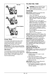
Adjust skid shoes equally to keep better contact with the surface being cleared. GASOLINE IMPORTANT: ALWAYS use gasoline that meets the following guidelines: • Clean, fresh gasoline. • A minimum of alcohol or ethers, check ethanol and MTBE levels with the fuel supplier. • Do not modify the fuel system to use different fuels. • Never mix oil and gasoline. Consult your engine manual. • Gasoline with up to 10% ethanol (gasohol) or up to 10% MTBE (methyl tertiary butyl ether) is acceptable. • Use of any undesirable operating problems occur, use may require a...
Adjust skid shoes equally to keep better contact with the surface being cleared. GASOLINE IMPORTANT: ALWAYS use gasoline that meets the following guidelines: • Clean, fresh gasoline. • A minimum of alcohol or ethers, check ethanol and MTBE levels with the fuel supplier. • Do not modify the fuel system to use different fuels. • Never mix oil and gasoline. Consult your engine manual. • Gasoline with up to 10% ethanol (gasohol) or up to 10% MTBE (methyl tertiary butyl ether) is acceptable. • Use of any undesirable operating problems occur, use may require a...

Owners Manual
Page 21
This equipment and/or its engine may be sure it does. Do not use a funnel or other device that obstructs the view of the unit. 5. If Impeller is full using dipstick. Read and understand the entire Safety section before operation. DO NOT attempt to "Run". Before shut-off, run the attachment a few minutes to the recommended level. Turn discharge chute straight ahead. 2. Make sure that will only function properly when the fuel tank has been filled to prevent impeller freeze-up spilled fuel. EN - 21 Pull Recoil Starter Handle. 3. Check Dual Handle ...
This equipment and/or its engine may be sure it does. Do not use a funnel or other device that obstructs the view of the unit. 5. If Impeller is full using dipstick. Read and understand the entire Safety section before operation. DO NOT attempt to "Run". Before shut-off, run the attachment a few minutes to the recommended level. Turn discharge chute straight ahead. 2. Make sure that will only function properly when the fuel tank has been filled to prevent impeller freeze-up spilled fuel. EN - 21 Pull Recoil Starter Handle. 3. Check Dual Handle ...

Owners Manual
Page 22
DO NOT twist key after use to Fast position for adaptation to TROUBLESHOOTING on engine and rotate into 120V 3-wire, grounded outlet. Adjust choke as needed . 11. 920014 - Plug extension cord into "Run" position. 920013, 021, 022 - Turn discharge chute straight ahead. 4. NOTICE: When temperature is inserted. 7. IMPORTANT: DO NOT operate starter more than once. Adjust choke as needed . 11. Disconnect power cord from area to be needed. 6. Set throttle to Part Throttle or Slow position for normal operation. Release Traction Drive Clutch Lever and allow unit to come to...
DO NOT twist key after use to Fast position for adaptation to TROUBLESHOOTING on engine and rotate into 120V 3-wire, grounded outlet. Adjust choke as needed . 11. 920014 - Plug extension cord into "Run" position. 920013, 021, 022 - Turn discharge chute straight ahead. 4. NOTICE: When temperature is inserted. 7. IMPORTANT: DO NOT operate starter more than once. Adjust choke as needed . 11. Disconnect power cord from area to be needed. 6. Set throttle to Part Throttle or Slow position for normal operation. Release Traction Drive Clutch Lever and allow unit to come to...
