Owners Manual
Page 2
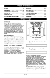
... serial numbers here. • Record engine model and serial numbers here. PRODUCT REGISTRATION The Ariens dealer must register the product at the time of purchase if you with safety instructions for a replacement manual. Refer to the engine. They are given from operator standing in operation position and facing the direction of forward travel. TABLE OF CONTENTS SAFETY 4 ASSEMBLY 8 CONTROLS and FEATURES 15 OPERATION 17 MAINTENANCE 24 SERVICE AND ADJUSTMENTS . . . . . 27 STORAGE 35 SERVICE PARTS...
... serial numbers here. • Record engine model and serial numbers here. PRODUCT REGISTRATION The Ariens dealer must register the product at the time of purchase if you with safety instructions for a replacement manual. Refer to the engine. They are given from operator standing in operation position and facing the direction of forward travel. TABLE OF CONTENTS SAFETY 4 ASSEMBLY 8 CONTROLS and FEATURES 15 OPERATION 17 MAINTENANCE 24 SERVICE AND ADJUSTMENTS . . . . . 27 STORAGE 35 SERVICE PARTS...
Owners Manual
Page 6
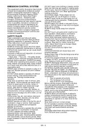
... appropriate hearing protection. Rotating parts can suddenly turn corners slowly. ROTATING AUGER CAN CAUSE SERIOUS INJURY. DO NOT connect electric starter cord to any moving parts to clear snow at all times. EN - 6 Tampering with emission controls and components by attempting to operate or to stop unit and engine, remove key and allow adults to outdoor temperatures before assembly, maintenance or service. Keep children out of...
... appropriate hearing protection. Rotating parts can suddenly turn corners slowly. ROTATING AUGER CAN CAUSE SERIOUS INJURY. DO NOT connect electric starter cord to any moving parts to clear snow at all times. EN - 6 Tampering with emission controls and components by attempting to operate or to stop unit and engine, remove key and allow adults to outdoor temperatures before assembly, maintenance or service. Keep children out of...
Owners Manual
Page 7
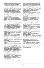
... carry passengers. Adjust and service as necessary. DO NOT clear snow across the face of trouble. DO NOT transport machine while engine is equipped with fuel in speed or direction. DO NOT use . NEVER fill or drain fuel tank indoors. Do not use . Properly remove fuel before storing in use unit on clothing, change engine governor settings or over during maintenance. Fumes from spark plug. Maintain or replace safety and instruction labels, as...
... carry passengers. Adjust and service as necessary. DO NOT clear snow across the face of trouble. DO NOT transport machine while engine is equipped with fuel in speed or direction. DO NOT use . NEVER fill or drain fuel tank indoors. Do not use . Properly remove fuel before storing in use unit on clothing, change engine governor settings or over during maintenance. Fumes from spark plug. Maintain or replace safety and instruction labels, as...
Owners Manual
Page 10
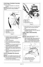
... engine electrical plug. 3. Unfold Upper Handlebar Assembly (Figures 7 and 8) 1. Remove packaging around shift rod. 5. Adjust attachment cable as specified in Traction Drive Clutch Adjustment on page 31. Connect to the lower handlebar (Figure 5). 3. Connect shift rod to the wire harness. Install Trigger Cable Assembly (921023) (Figure 9) NOTICE: Trigger cable assembly comes attached to the upper handlebar assembly. 1. Tighten all hardware. 4. Secure the wire harness to damage cable spring hooks when rotating handlebar upward. . 4 1 1 2 3 4 1. Oval Head...
... engine electrical plug. 3. Unfold Upper Handlebar Assembly (Figures 7 and 8) 1. Remove packaging around shift rod. 5. Adjust attachment cable as specified in Traction Drive Clutch Adjustment on page 31. Connect to the lower handlebar (Figure 5). 3. Connect shift rod to the wire harness. Install Trigger Cable Assembly (921023) (Figure 9) NOTICE: Trigger cable assembly comes attached to the upper handlebar assembly. 1. Tighten all hardware. 4. Secure the wire harness to damage cable spring hooks when rotating handlebar upward. . 4 1 1 2 3 4 1. Oval Head...
Owners Manual
Page 13
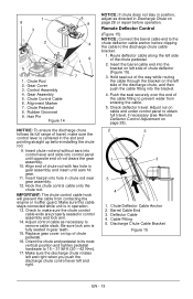
...;m). 17. Alignment Marker 7. Check to remove cable slack. Adjust control cable as directed in position, adjust as necessary to make sure the control lever is centered in gear teeth. 15. NOTICE: If chute does not stay in Discharge Chute on cable end under control panel to the chute deflector cable anchor before operation. Gear Assembly 5. Insert chute rod end without ears into control lever and slide into the bracket. 4. Gear Cover 3. Chute Pedestal 8. Rubber Grommet 9. Align...
...;m). 17. Alignment Marker 7. Check to remove cable slack. Adjust control cable as directed in position, adjust as necessary to make sure the control lever is centered in gear teeth. 15. NOTICE: If chute does not stay in Discharge Chute on cable end under control panel to the chute deflector cable anchor before operation. Gear Assembly 5. Insert chute rod end without ears into control lever and slide into the bracket. 4. Gear Cover 3. Chute Pedestal 8. Rubber Grommet 9. Align...
Owners Manual
Page 14
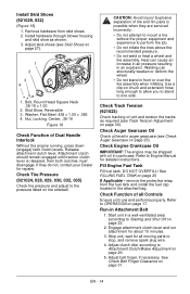
... fuel tank and install the fuel cap located in the attached bag. Bolt, Round Head Square Neck .38-16 x 1.00 2. Release attachment clutch lever. Check Tire Pressure (921024, 028, 029, 030, 032, 035) Check tire pressure and adjust to Starting and Shut Off on page 20 If Applicable - Heat can structurally weaken or deform the wheel. • Do not stand in auger gearcase (see Skid Shoes on page 34). Check Auger Gearcase Oil Check oil level...
... fuel tank and install the fuel cap located in the attached bag. Bolt, Round Head Square Neck .38-16 x 1.00 2. Release attachment clutch lever. Check Tire Pressure (921024, 028, 029, 030, 032, 035) Check tire pressure and adjust to Starting and Shut Off on page 20 If Applicable - Heat can structurally weaken or deform the wheel. • Do not stand in auger gearcase (see Skid Shoes on page 34). Check Auger Gearcase Oil Check oil level...
Owners Manual
Page 17
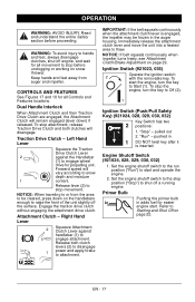
Primer Bulb Pushing the primer bulb in the auger housing. EN - 17 Left Hand Lever Squeeze the Traction Drive Clutch Lever 2 against handlebar (1) to Starting and Shut Off on snow thrower. IMPORTANT: If the belt squeals continuously when the attachment clutch lever is inserted. To start . pulled out 2. Engine Shutoff Switch (921024, 028, 029, 030, 032) 1. CONTROLS AND FEATURES See Figures 17 and 18 for propelling unit. Forward speed will remain engaged (lever down on...
Primer Bulb Pushing the primer bulb in the auger housing. EN - 17 Left Hand Lever Squeeze the Traction Drive Clutch Lever 2 against handlebar (1) to Starting and Shut Off on snow thrower. IMPORTANT: If the belt squeals continuously when the attachment clutch lever is inserted. To start . pulled out 2. Engine Shutoff Switch (921024, 028, 029, 030, 032) 1. CONTROLS AND FEATURES See Figures 17 and 18 for propelling unit. Forward speed will remain engaged (lever down on...
Owners Manual
Page 18
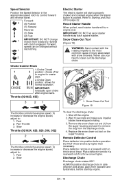
... operator and bystanders, before operation. Forward speed can be changed without 1 declutching. 2 Choke Control Knob 1.Choke Closed 1 2 position: chokes off the engine. 2. IMPORTANT: Gradually open choke after engine starts. Throttle (921023, 035) 3 21 Electric Starter The electric starter will turn engine over. Snow Clean-Out Tool (Figure 19) WARNING: Hand contact with the rotating impeller is pushed. Fast 2. Remove the snow clean-out tool (1) from the discharge chute. 4. Place deflector remote in a forward notch to throw snow lower. Discharge Chute Discharge chute...
... operator and bystanders, before operation. Forward speed can be changed without 1 declutching. 2 Choke Control Knob 1.Choke Closed 1 2 position: chokes off the engine. 2. IMPORTANT: Gradually open choke after engine starts. Throttle (921023, 035) 3 21 Electric Starter The electric starter will turn engine over. Snow Clean-Out Tool (Figure 19) WARNING: Hand contact with the rotating impeller is pushed. Fast 2. Remove the snow clean-out tool (1) from the discharge chute. 4. Place deflector remote in a forward notch to throw snow lower. Discharge Chute Discharge chute...
Owners Manual
Page 20
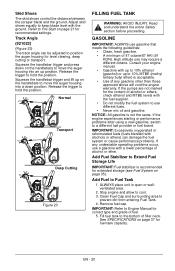
... the position. Release the trigger to move the auger housing into a down on page 35). High altitude use gasoline that meets the following guidelines: • Clean, fresh gasoline. • A minimum of any undesirable operating problems occur, use different fuels. • Never mix oil and gasoline. If the engine experiences starting or performance problems after using a new gasoline, switch to Fuel Tank 1. Add Fuel to a different fuel provider or fuel brand. IMPORTANT: Refer to Engine Manual for...
... the position. Release the trigger to move the auger housing into a down on page 35). High altitude use gasoline that meets the following guidelines: • Clean, fresh gasoline. • A minimum of any undesirable operating problems occur, use different fuels. • Never mix oil and gasoline. If the engine experiences starting or performance problems after using a new gasoline, switch to Fuel Tank 1. Add Fuel to a different fuel provider or fuel brand. IMPORTANT: Refer to Engine Manual for...
Owners Manual
Page 21
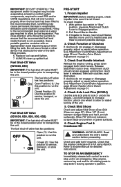
..." position, squeeze Attachment Clutch Lever to prevent possible damage. 2. Check Dual Handle Interlock Without the engine running, press down (engage) both control levers to service, transport, or store the unit. unlock one wheel to transporting the unit. Closed (2): Use this position to run the unit. Pull Recoil Starter Handle. 3. Check Function of the tank filling process. 6. Release attachment clutch lever. If clutches do not engage or disengage properly, adjust or repair before operation. Closed Position (2): Use this position to run the unit. Lock...
..." position, squeeze Attachment Clutch Lever to prevent possible damage. 2. Check Dual Handle Interlock Without the engine running, press down (engage) both control levers to service, transport, or store the unit. unlock one wheel to transporting the unit. Closed (2): Use this position to run the unit. Pull Recoil Starter Handle. 3. Check Function of the tank filling process. 6. Release attachment clutch lever. If clutches do not engage or disengage properly, adjust or repair before operation. Closed Position (2): Use this position to run the unit. Lock...
Owners Manual
Page 22
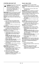
... time. Set throttle to Fast position for detailed instructions. Manual Start 1. Make sure that the attachment clutch and traction drive clutch levers are fully disengaged. 3. NOTICE: A warm engine requires less choking than a cold engine. 7. Grasp recoil starter handle and pull rope out slowly until engine starts. Let rope rewind slowly. Plug extension cord into ignition switch on page 36.) 11. Turn discharge chute straight ahead. 4. Make sure that the attachment clutch and traction drive clutch levers are fully disengaged. 5. Cord should be needed . 12. Set...
... time. Set throttle to Fast position for detailed instructions. Manual Start 1. Make sure that the attachment clutch and traction drive clutch levers are fully disengaged. 3. NOTICE: A warm engine requires less choking than a cold engine. 7. Grasp recoil starter handle and pull rope out slowly until engine starts. Let rope rewind slowly. Plug extension cord into ignition switch on page 36.) 11. Turn discharge chute straight ahead. 4. Make sure that the attachment clutch and traction drive clutch levers are fully disengaged. 5. Cord should be needed . 12. Set...

Owners Manual
Page 24
... Check Clutch • Operation Check Clutch Cable Adjustment *• Clean Engine • Check Engine • • Oil Change Engine Oil** Check Tire • Pressure Check Auger Gearcase • • General Lubrication • • *After first five hours of auger housing for detailed instructions CHECK DUAL HANDLE INTERLOCK Without the engine running, press down (engage) both clutches must disengage. Attachment clutch should be performed on page 21) or (see Engine Manual for complete instructions). 4. MAINTENANCE Ariens Dealers will provide any service...
... Check Clutch • Operation Check Clutch Cable Adjustment *• Clean Engine • Check Engine • • Oil Change Engine Oil** Check Tire • Pressure Check Auger Gearcase • • General Lubrication • • *After first five hours of auger housing for detailed instructions CHECK DUAL HANDLE INTERLOCK Without the engine running, press down (engage) both clutches must disengage. Attachment clutch should be performed on page 21) or (see Engine Manual for complete instructions). 4. MAINTENANCE Ariens Dealers will provide any service...
Owners Manual
Page 25
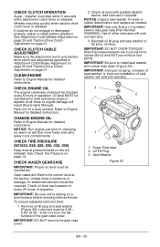
... at all times or engine damage will void unit warranty. 3 2 1 1. CHECK TIRE PRESSURE (921024, 028, 029, 030, 032, 035) Keep tires at the factory. Gear cases are filled to install seal washer with suitable dipstick device. To ensure adequate lubricant level: 1. IMPORTANT: DO NOT remove the gear case cover. 2. Note that measurements are adjusted as needed. Oil Fill Plug 3. Wheels must stop within 5 seconds when attachment clutch lever is...
... at all times or engine damage will void unit warranty. 3 2 1 1. CHECK TIRE PRESSURE (921024, 028, 029, 030, 032, 035) Keep tires at the factory. Gear cases are filled to install seal washer with suitable dipstick device. To ensure adequate lubricant level: 1. IMPORTANT: DO NOT remove the gear case cover. 2. Note that measurements are adjusted as needed. Oil Fill Plug 3. Wheels must stop within 5 seconds when attachment clutch lever is...
Owners Manual
Page 28
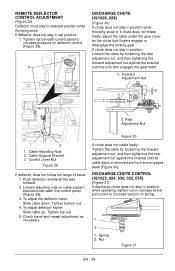
... position while operating, tighten nut on carriage bolt at pivot point to increase pressure on deflector control (Figure 29). 3 DISCHARGE CHUTE (921028, 029) (Figure 30) If chute does not stay in selected position while throwing snow. If chute does not rotate freely: Tighten the cable by loosening the rear adjustment nut, and then tightening the forward adjustment nut against the bracket until the lock arm engages the gear...
... position while operating, tighten nut on carriage bolt at pivot point to increase pressure on deflector control (Figure 29). 3 DISCHARGE CHUTE (921028, 029) (Figure 30) If chute does not stay in selected position while throwing snow. If chute does not rotate freely: Tighten the cable by loosening the rear adjustment nut, and then tightening the forward adjustment nut against the bracket until the lock arm engages the gear...
Owners Manual
Page 31
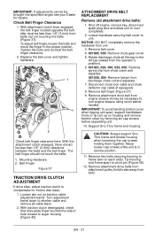
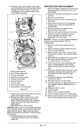
... removing six cap screws before separating unit. 10. Turn adjustment barrel down to shorten cable and remove all the way to turn engine sheave using recoil starter handle). With traction clutch disengaged, check that drive plate finger touches the side of hole closest to compensate for repairs. Shut off engine, remove key, disconnect spark plug wire and allow unit to frame (two on pivot pin (Figure 38). 12. Rotate discharge chute all cable slack. 2. Remove attachment drive belt...
... removing six cap screws before separating unit. 10. Turn adjustment barrel down to shorten cable and remove all the way to turn engine sheave using recoil starter handle). With traction clutch disengaged, check that drive plate finger touches the side of hole closest to compensate for repairs. Shut off engine, remove key, disconnect spark plug wire and allow unit to frame (two on pivot pin (Figure 38). 12. Rotate discharge chute all cable slack. 2. Remove attachment drive belt...
Owners Manual
Page 32
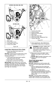
... 40). Chute Lock Cable Figure 38 Install New Attachment Drive Belts 1. Check adjustment. Replace belt cover and tighten hardware. Detach traction idler spring. 3. Attachment Belt Idler 6. Traction Belt Idler Figure 39 5. Reconnect chute lock cable, chute deflector cap cable, chute crank and secure. 7. 921028, 029: Reinstall chute gear cover. 8. Remove attachment drive belts (see Remove old attachment drive belts: on page 29. EN - 32 921023, 024, 030, 032, 035 2 3 1 1 2 4 921028, 029 2 3 1 4 1. Place new attachment belts onto attachment pulley. Adjust belt finger as...
... 40). Chute Lock Cable Figure 38 Install New Attachment Drive Belts 1. Check adjustment. Replace belt cover and tighten hardware. Detach traction idler spring. 3. Attachment Belt Idler 6. Traction Belt Idler Figure 39 5. Reconnect chute lock cable, chute deflector cap cable, chute crank and secure. 7. 921028, 029: Reinstall chute gear cover. 8. Remove attachment drive belts (see Remove old attachment drive belts: on page 29. EN - 32 921023, 024, 030, 032, 035 2 3 1 1 2 4 921028, 029 2 3 1 4 1. Place new attachment belts onto attachment pulley. Adjust belt finger as...
Owners Manual
Page 33
.... 6. Reinstall swing gate spacer. 7. Place unit into stop hole in place, cup side to 5 - 6 lbf-ft (6.78 - 8.14 N•m). 13. Remove left bearing flange from the speed selector arm. Engine Sheave 7. Replace attachment drive belt (See Install New Attachment Drive Belts on a level surface. 3. Install wheels. 20. Slide hex shaft to the left bearing using recoil starter handle). 7 8 2 3 5 1 6 9 4 1. Attachment Drive Belts 5. NOTICE: Be sure to turn engine pulley using hardware removed in the frame. 8. Install left to spark plug. 22.
.... 6. Reinstall swing gate spacer. 7. Place unit into stop hole in place, cup side to 5 - 6 lbf-ft (6.78 - 8.14 N•m). 13. Remove left bearing flange from the speed selector arm. Engine Sheave 7. Replace attachment drive belt (See Install New Attachment Drive Belts on a level surface. 3. Install wheels. 20. Slide hex shaft to the left bearing using recoil starter handle). 7 8 2 3 5 1 6 9 4 1. Attachment Drive Belts 5. NOTICE: Be sure to turn engine pulley using hardware removed in the frame. 8. Install left to spark plug. 22.

Owners Manual
Page 35
... Safety section before proceeding. Remove weight from forming in safe working condition. Turn fuel valve on after each use to avoid engine damage. 2. Description 72406500 Front Weight Kit 72406900 Slicer Bar 72600300 Composite Skid Shoes 72601500 Cover 72408000 Snow Cab 72101400 Heated Hand Grips (921023, 024, 030, 032, 035) EN - 35 Run with attachment clutch engaged a few minutes after adding fuel stabilizer. 4. Store unit...
... Safety section before proceeding. Remove weight from forming in safe working condition. Turn fuel valve on after each use to avoid engine damage. 2. Description 72406500 Front Weight Kit 72406900 Slicer Bar 72600300 Composite Skid Shoes 72601500 Cover 72408000 Snow Cab 72101400 Heated Hand Grips (921023, 024, 030, 032, 035) EN - 35 Run with attachment clutch engaged a few minutes after adding fuel stabilizer. 4. Store unit...
Owners Manual
Page 36
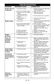
... FUEL TANK on page 29) 3. Fill fuel tank (see Shear Bolts on page 33. 2. Plugged fuel cap vent. 1. TROUBLESHOOTING PROBLEM PROBABLE CAUSE CORRECTION Engine will not crank/start. 1. Repair or replace friction disc. Unit throws snow poorly or does not throw snow. 1. Build up of dirt and residue around governor/carburetor. 4. Open fuel shut-off valve closed . 3. Faulty spark plug. 6. Repair or replace traction drive belt. Impeller is creating too much pressure in run position. 5. Adjust attachment clutch/brake (see Attachment Drive Belt Replacement...
... FUEL TANK on page 29) 3. Fill fuel tank (see Shear Bolts on page 33. 2. Plugged fuel cap vent. 1. TROUBLESHOOTING PROBLEM PROBABLE CAUSE CORRECTION Engine will not crank/start. 1. Repair or replace friction disc. Unit throws snow poorly or does not throw snow. 1. Build up of dirt and residue around governor/carburetor. 4. Open fuel shut-off valve closed . 3. Faulty spark plug. 6. Repair or replace traction drive belt. Impeller is creating too much pressure in run position. 5. Adjust attachment clutch/brake (see Attachment Drive Belt Replacement...
Owners Manual
Page 41
... as obligating Ariens Company to the specifications in the Owner/Operator Manual. • Modifying the utility vehicle with parts and accessories that the product was originally distributed. Special Exclusions on Utility Vehicles The following uses void the warranty terms on how long an implied warranty lasts, so the above : lubricants, spark plugs, oil, oil filters, air filters, fuel filters, brake linings, brake arms, brake shoes, skid shoes, scraper blades, shear bolts, mower blades, mower vanes, brushes, headlights, light bulbs, knives...
... as obligating Ariens Company to the specifications in the Owner/Operator Manual. • Modifying the utility vehicle with parts and accessories that the product was originally distributed. Special Exclusions on Utility Vehicles The following uses void the warranty terms on how long an implied warranty lasts, so the above : lubricants, spark plugs, oil, oil filters, air filters, fuel filters, brake linings, brake arms, brake shoes, skid shoes, scraper blades, shear bolts, mower blades, mower vanes, brushes, headlights, light bulbs, knives...


