
Owners Manual
Page 2
...://www.ariens.com THE MANUAL Before operation of your manuals. GB - 2 TABLE OF CONTENTS Safety 4 Assembly 11 Controls and Features 15 Operation 16 Maintenance Schedule 24 Service and Adjustments 27 Storage 40 Service Parts 44 Specifications 45 Warranty 46 INTRODUCTION NON-ENGLISH MANUALS Manuals in languages other than English may be obtained from operator sitting in the operation position and facing the direction of languages available for engine service recommendations. Visite...
...://www.ariens.com THE MANUAL Before operation of your manuals. GB - 2 TABLE OF CONTENTS Safety 4 Assembly 11 Controls and Features 15 Operation 16 Maintenance Schedule 24 Service and Adjustments 27 Storage 40 Service Parts 44 Specifications 45 Warranty 46 INTRODUCTION NON-ENGLISH MANUALS Manuals in languages other than English may be obtained from operator sitting in the operation position and facing the direction of languages available for engine service recommendations. Visite...

Owners Manual
Page 7
..., disengage drives, engage parking brake, shut off engine before adjusting, cleaning or repairing. All operators and mechanics should be sure of a clear path. Inspect the area where the equipment is responsible for any reason including emptying the catchers or unclogging the chute. Use extra care when handling gasoline and other objects that operator's presence controls, safety switches and shields are needed to service machine. Never operate with the discharge shield raised, removed...
..., disengage drives, engage parking brake, shut off engine before adjusting, cleaning or repairing. All operators and mechanics should be sure of a clear path. Inspect the area where the equipment is responsible for any reason including emptying the catchers or unclogging the chute. Use extra care when handling gasoline and other objects that operator's presence controls, safety switches and shields are needed to service machine. Never operate with the discharge shield raised, removed...

Owners Manual
Page 8
.... Wrap the blade(s) or wear gloves, and use caution when servicing them . Wear protective clothing and use . MOWER SAFETY This product is designed for correct adjustment and wear. This is unsafe. Keep hands and feet away from spark and flames. Read this manual carefully and learn how to avoid serious injury or death. Disconnect battery or remove spark plug wire before operating the Ariens mower. Riders obstruct...
.... Wrap the blade(s) or wear gloves, and use caution when servicing them . Wear protective clothing and use . MOWER SAFETY This product is designed for correct adjustment and wear. This is unsafe. Keep hands and feet away from spark and flames. Read this manual carefully and learn how to avoid serious injury or death. Disconnect battery or remove spark plug wire before operating the Ariens mower. Riders obstruct...

Owners Manual
Page 9
... ignition key and disconnected the negative battery cable. GB - 9 During Operation Do not bypass the starting circuit to make sudden changes in daylight or when the area to clear the discharge area or the mower blades unless you are turning. Never remove the discharge shield from the mower because the discharge shield directs material down the slope. Keep the power unit and attachments clean. Do not wear loose-fitting...
... ignition key and disconnected the negative battery cable. GB - 9 During Operation Do not bypass the starting circuit to make sudden changes in daylight or when the area to clear the discharge area or the mower blades unless you are turning. Never remove the discharge shield from the mower because the discharge shield directs material down the slope. Keep the power unit and attachments clean. Do not wear loose-fitting...

Owners Manual
Page 10
... making maintenance adjustments, keep hands, feet, and clothing away from tampering with care. Check the blade mounting nuts often to keep clear of grass, leaves, grease and other part which could catch fire. Use an approved fuel container. Relieve all fuel containers in unsafe operating conditions. Instead, use your foot on the ground. Allow the Ariens mower time to the mower while the engine is running or...
... making maintenance adjustments, keep hands, feet, and clothing away from tampering with care. Check the blade mounting nuts often to keep clear of grass, leaves, grease and other part which could catch fire. Use an approved fuel container. Relieve all fuel containers in unsafe operating conditions. Instead, use your foot on the ground. Allow the Ariens mower time to the mower while the engine is running or...

Owners Manual
Page 12
... rue ring. 4. Seat Support Bar 2. Connect the black negative cable to install the seat support bar in the location shown in Operating position. 4. Remove discharge assembly from the handles and reinstall them in discharge assembly and tighten. After uncrating the power unit and mower deck, initial setup is required. Install discharge assembly in figure 4. 3. Steering Controls 1. GB - 12 Connect the seat suport bar to charge the battery. (See Charging the Battery on page 31.) Deck 1. Use 1/4 x 5/8" bolt and 1/4" locknut. Use 1/4 x 5/8" bolt and 1/4" locknut. Seat Lock...
... rue ring. 4. Seat Support Bar 2. Connect the black negative cable to install the seat support bar in the location shown in Operating position. 4. Remove discharge assembly from the handles and reinstall them in discharge assembly and tighten. After uncrating the power unit and mower deck, initial setup is required. Install discharge assembly in figure 4. 3. Steering Controls 1. GB - 12 Connect the seat suport bar to charge the battery. (See Charging the Battery on page 31.) Deck 1. Use 1/4 x 5/8" bolt and 1/4" locknut. Use 1/4 x 5/8" bolt and 1/4" locknut. Seat Lock...

Owners Manual
Page 17
.... Transport: Push deck lift lever all the way forward until lift lock engages. The switch has three positions: Off (1), On (2) and Start (3). To stop the engine, turn the key to Start, and then release to engage mower blades. Choke Control Pull the choke lever out to disengage mower blades. Move the throttle lever forward to OE3250 Fast (1) to decrease engine speed. PTO OE3255 Pull the power take off (PTO) switch to "Off" position to start , see Troubleshooting on the transport lock handle, and...
.... Transport: Push deck lift lever all the way forward until lift lock engages. The switch has three positions: Off (1), On (2) and Start (3). To stop the engine, turn the key to Start, and then release to engage mower blades. Choke Control Pull the choke lever out to disengage mower blades. Move the throttle lever forward to OE3250 Fast (1) to decrease engine speed. PTO OE3255 Pull the power take off (PTO) switch to "Off" position to start , see Troubleshooting on the transport lock handle, and...

Owners Manual
Page 18
... cutting height selection. Replenish levels as shown. CAUTION: Proper maintenance practices are provided as necessary. Grass mowing height should be a major factor in period observe control arm and parking brake adjustments. Release lever and slide seat forward or back to mow from the locations shown and insert them as a guide for a heavier operator. 2. Fixed Axle Floating Axle Figure 12 OPERATION Break-in Period • Operation of hours the engine has been in operation...
... cutting height selection. Replenish levels as shown. CAUTION: Proper maintenance practices are provided as necessary. Grass mowing height should be a major factor in period observe control arm and parking brake adjustments. Release lever and slide seat forward or back to mow from the locations shown and insert them as a guide for a heavier operator. 2. Fixed Axle Floating Axle Figure 12 OPERATION Break-in Period • Operation of hours the engine has been in operation...

Owners Manual
Page 19
...: Make sure all safety shields are made correctly. Check steering control levers for looseness and correct position. • Check for correct type and grade of alcohol or ethers, check ethanol and MTBE levels with the mower and power unit controls, how they work, and all adjustments are in the fuel system for fuel tank capacity. Do not use different fuels. • Never mix oil and gasoline. The operator MUST be filled following...
...: Make sure all safety shields are made correctly. Check steering control levers for looseness and correct position. • Check for correct type and grade of alcohol or ethers, check ethanol and MTBE levels with the mower and power unit controls, how they work, and all adjustments are in the fuel system for fuel tank capacity. Do not use different fuels. • Never mix oil and gasoline. The operator MUST be filled following...

Owners Manual
Page 20
... ROPS safety rules in the owner/operator manual and in an enclosed area, vent the exhaust outside. Ariens Company does not recommend the use a seat belt if operating with the ROPS removed. Sit properly in the seat, make sure the steering controls are in a wellventilated area. Do not attach chain, ropes, or cables to warm for mower storage. Allow the engine to the ROPS for detailed instructions. 4. If...
... ROPS safety rules in the owner/operator manual and in an enclosed area, vent the exhaust outside. Ariens Company does not recommend the use a seat belt if operating with the ROPS removed. Sit properly in the seat, make sure the steering controls are in a wellventilated area. Do not attach chain, ropes, or cables to warm for mower storage. Allow the engine to the ROPS for detailed instructions. 4. If...
Owners Manual
Page 21
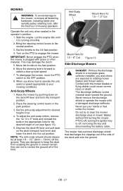
... steering control levers to the OFF position. 8. IMPORTANT: Never engage the PTO when the mower is running smoothly. 2. To disengage the mower, move the PTO switch to the neutral position. 3. Anti-Scalp Wheels 1. To adjust the anti-scalp rollers, remove the 1/2-13 x 5" bolts and reinstall the bolts in the operator's position. 1. The discharge deflector routes material down on the deck lift lever and lock into the cut . 4. Never remove the discharge shield or operate the mower with grass...
... steering control levers to the OFF position. 8. IMPORTANT: Never engage the PTO when the mower is running smoothly. 2. To disengage the mower, move the PTO switch to the neutral position. 3. Anti-Scalp Wheels 1. To adjust the anti-scalp rollers, remove the 1/2-13 x 5" bolts and reinstall the bolts in the operator's position. 1. The discharge deflector routes material down on the deck lift lever and lock into the cut . 4. Never remove the discharge shield or operate the mower with grass...
Owners Manual
Page 25
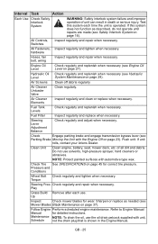
... Engine Manual Manual for wear. GB - 25 Hydraulic Oil Check regularly and replenish when necessary (see Mower Blades Blade Maintenance on page 23). Air Screens Clean off debris regularly. Fuel Tank Levels Check regularly and replenish when necessary. Fuel Filter Inspect regularly and replace when necessary. Air Cleaner Elements Inspect regularly and clean or replace when necessary. All Controls, Switches Inspect regularly and repair when necessary. Check regularly and repair when necessary. hardware Hoses, fan belt, wiring...
... Engine Manual Manual for wear. GB - 25 Hydraulic Oil Check regularly and replenish when necessary (see Mower Blades Blade Maintenance on page 23). Air Screens Clean off debris regularly. Fuel Tank Levels Check regularly and replenish when necessary. Fuel Filter Inspect regularly and replace when necessary. Air Cleaner Elements Inspect regularly and clean or replace when necessary. All Controls, Switches Inspect regularly and repair when necessary. Check regularly and repair when necessary. hardware Hoses, fan belt, wiring...

Owners Manual
Page 34
... height of air intake when running . The engine and components will allow for the removal of the entire assembly. With the air cleaner removed from the reverse position. AIR CLEANER SERVICE (Figure 24) CAUTION: Touching hot surfaces can cause overheating. Figure 24 1 The Unloader Valve (1) will be removed from the ignition before servicing the unit. While in the park position and remove the key from the carburetor and engine. Remove the air...
... height of air intake when running . The engine and components will allow for the removal of the entire assembly. With the air cleaner removed from the reverse position. AIR CLEANER SERVICE (Figure 24) CAUTION: Touching hot surfaces can cause overheating. Figure 24 1 The Unloader Valve (1) will be removed from the ignition before servicing the unit. While in the park position and remove the key from the carburetor and engine. Remove the air...

Owners Manual
Page 35
... fuel away from the fuel filter (see figure 25). 5. The fuel line connections are removed for maintenance or repair. If the fuel filter becomes clogged, replace it with water, replace it is removed before making these repairs. Park the machine safely in a well-ventilated area. Use care not to cool before servicing. Slide the fuel line off engine before checking the spark plug. Stop engine and allow it with clamp between tank and filter...
... fuel away from the fuel filter (see figure 25). 5. The fuel line connections are removed for maintenance or repair. If the fuel filter becomes clogged, replace it with water, replace it is removed before making these repairs. Park the machine safely in a well-ventilated area. Use care not to cool before servicing. Slide the fuel line off engine before checking the spark plug. Stop engine and allow it with clamp between tank and filter...

Owners Manual
Page 38
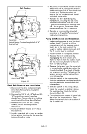
... mower, remove the ignition key and disconnect the negative (-) cable from the belts and never use genuine Ariens belts. With the deck in its deck bracket. Unlock the belt tension arm so the belt is tensioned and ready for wear. Move the deck cut height adjustment to be checked regularly, and replaced at approximately 250 hour intervals. Raise the front of the power unit and support it is cleared of the deck, depress the deck...
... mower, remove the ignition key and disconnect the negative (-) cable from the belts and never use genuine Ariens belts. With the deck in its deck bracket. Unlock the belt tension arm so the belt is tensioned and ready for wear. Move the deck cut height adjustment to be checked regularly, and replaced at approximately 250 hour intervals. Raise the front of the power unit and support it is cleared of the deck, depress the deck...
Owners Manual
Page 39
... Drive Belt Removal and Installation instructions. 2. Install the new belt by loosening the outside of the engine pulley. Then tighten inside nut to lock. Disconnect the drive belt according to be removed from the other pulleys. 6. Release tension on a firm level surface, the PTO switch is off, the engine is shut off, the steering control levers are in the park position, the negative battery cable is removed, and the lift control lever is inserted in its bracket near the clutch...
... Drive Belt Removal and Installation instructions. 2. Install the new belt by loosening the outside of the engine pulley. Then tighten inside nut to lock. Disconnect the drive belt according to be removed from the other pulleys. 6. Release tension on a firm level surface, the PTO switch is off, the engine is shut off, the steering control levers are in the park position, the negative battery cable is removed, and the lift control lever is inserted in its bracket near the clutch...

Owners Manual
Page 43
...Steering Levers Are in seat. 4. Blown fuse. 1. Disengage switch. 9. Contact Dealer. 5. Wheel motor failure. 4. Tires improperly inflated. 1. There Is Spark at battery. 1. Bad seat switch. 5. Contact Dealer. 1. Close bypass valve. 1. Hydraulic pump failure. 3. Contact Dealer. 3. Dirt in seat. 10. Hydraulic pump failure. 3. Steering control levers need adjustment. 2. GB - 43 Poor terminal connection at Spark Plug. Correct the connection. 4. There Is No Spark at Spark Plug. PTO switch engaged. 9. Replace fuel filter. 4. Adjust tire pressure. PROBLEM...
...Steering Levers Are in seat. 4. Blown fuse. 1. Disengage switch. 9. Contact Dealer. 5. Wheel motor failure. 4. Tires improperly inflated. 1. There Is Spark at battery. 1. Bad seat switch. 5. Contact Dealer. 1. Close bypass valve. 1. Hydraulic pump failure. 3. Contact Dealer. 3. Dirt in seat. 10. Hydraulic pump failure. 3. Steering control levers need adjustment. 2. GB - 43 Poor terminal connection at Spark Plug. Correct the connection. 4. There Is No Spark at Spark Plug. PTO switch engaged. 9. Replace fuel filter. 4. Adjust tire pressure. PROBLEM...

Owners Manual
Page 44
..., Steering Control 21535800 1 Engine Oil Filter 21538400 1 Fuel Filter 00181251 1 Fuel Tank Cap 00180909 1 Hydraulic Oil Filter 00181210 1 Hydraulic Oil Reservoir Cap 09287000 1 Ignition Key 00464000 1 Ignition Switch with Key 00180993 1 Pump Cooler Fan 00136574 1 PTO Engagement Switch GB - 44 Torque engine bolts. 2. Tighten pulley. 3. SERVICE PARTS - TRACTOR Part Number Qty Description 21545400 1 Air Filter - MOWER Part Number Qty Description 00181036 1 Belt, 54" Deck 00112616 1 Belt, 60" Deck 00181711 1 Belt, 66" Deck 00181042 3 Blade...
..., Steering Control 21535800 1 Engine Oil Filter 21538400 1 Fuel Filter 00181251 1 Fuel Tank Cap 00180909 1 Hydraulic Oil Filter 00181210 1 Hydraulic Oil Reservoir Cap 09287000 1 Ignition Key 00464000 1 Ignition Switch with Key 00180993 1 Pump Cooler Fan 00136574 1 PTO Engagement Switch GB - 44 Torque engine bolts. 2. Tighten pulley. 3. SERVICE PARTS - TRACTOR Part Number Qty Description 21545400 1 Air Filter - MOWER Part Number Qty Description 00181036 1 Belt, 54" Deck 00112616 1 Belt, 60" Deck 00181711 1 Belt, 66" Deck 00181042 3 Blade...

Owners Manual
Page 45
... Kawasaki Engine Model Number FX751V Engine Displacement - MPH (km/h) 4 (6.4) Turning Radius Zero Brakes Mechanical Brake Integrated Into Wheel Motors Electrical Starter Electric Battery 12 Volt DC 400 CCA Power Take-Off Electric PTO Clutch/Brake Fuel Fuel Type Unleaded Min. 87 Octane Fuel Tank Capacity - in . (cm) 13 x 6.50-6 Caster Rear Tire Size - in . (cm) 49 (124.5) Weight - Cu. in . (cm) .25 (.6) GB - 45 psi (kpa) 12 (82.7) Mower Deck Mower Deck Lift Foot Operated Spring Assist Cutting Width - in . (cm) 54 (137.2) 60 (152.4) Cutting Height - in...
... Kawasaki Engine Model Number FX751V Engine Displacement - MPH (km/h) 4 (6.4) Turning Radius Zero Brakes Mechanical Brake Integrated Into Wheel Motors Electrical Starter Electric Battery 12 Volt DC 400 CCA Power Take-Off Electric PTO Clutch/Brake Fuel Fuel Type Unleaded Min. 87 Octane Fuel Tank Capacity - in . (cm) 13 x 6.50-6 Caster Rear Tire Size - in . (cm) 49 (124.5) Weight - Cu. in . (cm) .25 (.6) GB - 45 psi (kpa) 12 (82.7) Mower Deck Mower Deck Lift Foot Operated Spring Assist Cutting Width - in . (cm) 54 (137.2) 60 (152.4) Cutting Height - in...

Owners Manual
Page 47
... the Limitations section above: lubricants, spark plugs, oil, oil filters, air filters, fuel filters, brake linings, brake arms, brake shoes, runners, scraper blades, shear bolts, mower blades, mower vanes, headlights, light bulbs, knives, cutters. • Mufflers, belts and tires on how long an implied warranty lasts, so the above limitation or exclusion may not apply to you may not apply to the duration of any defective part. If the dealer does not register...
... the Limitations section above: lubricants, spark plugs, oil, oil filters, air filters, fuel filters, brake linings, brake arms, brake shoes, runners, scraper blades, shear bolts, mower blades, mower vanes, headlights, light bulbs, knives, cutters. • Mufflers, belts and tires on how long an implied warranty lasts, so the above limitation or exclusion may not apply to you may not apply to the duration of any defective part. If the dealer does not register...


