
Owners Manual
Page 1
... No. 10000 and up ) 915173 - Zoom XL 54 (Serial No. 10000 and up) Gasoline containing up to 10% ethanol (E10) or up to 10% MTBE (methyl tertiary butyl ether) is acceptable for use ...) sur cette machine.L'utilisation d'une essence contenant plus de 10% d'éthanol (E10) ou de 10% de MTBE annulent la garantie. Zoom XL 48 (Serial No. 10000 and up ) 915165 - Zoom XL® Owner/Operator Manual Manuel Du Propriétaire/Utilisateur Models 915163 - ENGLISH FRANÇAIS 04043500A 9/11 Printed in this machine...
... No. 10000 and up ) 915173 - Zoom XL 54 (Serial No. 10000 and up) Gasoline containing up to 10% ethanol (E10) or up to 10% MTBE (methyl tertiary butyl ether) is acceptable for use ...) sur cette machine.L'utilisation d'une essence contenant plus de 10% d'éthanol (E10) ou de 10% de MTBE annulent la garantie. Zoom XL 48 (Serial No. 10000 and up ) 915165 - Zoom XL® Owner/Operator Manual Manuel Du Propriétaire/Utilisateur Models 915163 - ENGLISH FRANÇAIS 04043500A 9/11 Printed in this machine...

Owners Manual
Page 2
...are also available as a free download on the frame of unit, carefully and completely read your Dealer. Visit your dealer or www.ariens.com for engine service recommendations. También puede imprimir manuales en idiomas diferentes del inglés descargándolos gratuitamente de nuestra p&#...225;gina Web: http://www.ariens.com MANUELS NON ANGLAIS Des manuels dans différentes langues sont disponibles chez votre revendeur. All reference to left, right, front, ...
...are also available as a free download on the frame of unit, carefully and completely read your Dealer. Visit your dealer or www.ariens.com for engine service recommendations. También puede imprimir manuales en idiomas diferentes del inglés descargándolos gratuitamente de nuestra p&#...225;gina Web: http://www.ariens.com MANUELS NON ANGLAIS Des manuels dans différentes langues sont disponibles chez votre revendeur. All reference to left, right, front, ...
Owners Manual
Page 3
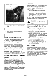
... and instruction by your retailer, it is returned. GB - 3 Keep a proof of the unit. UNAUTHORIZED REPLACEMENT PARTS Use only Ariens replacement parts. Before Attempting To Operate Your Unit: 1. Review control functions and operation of purchase if you do not understand or have...company process warranty claims or contact you do not register your responsibility to discontinue, change, and improve its products at printing. Ariens disclaims liability for assistance. Registering the product will be honored, whether or not the product registration card is your unit. Equipment...
... and instruction by your retailer, it is returned. GB - 3 Keep a proof of the unit. UNAUTHORIZED REPLACEMENT PARTS Use only Ariens replacement parts. Before Attempting To Operate Your Unit: 1. Review control functions and operation of purchase if you do not understand or have...company process warranty claims or contact you do not register your responsibility to discontinue, change, and improve its products at printing. Ariens disclaims liability for assistance. Registering the product will be honored, whether or not the product registration card is your unit. Equipment...
Owners Manual
Page 4
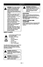
Disengage attachment, stop unit and engine, remove key, engage parking brake, and allow moving parts to point out important safety precautions. SAFETY DECALS AND LOCATIONS ALWAYS replace missing or damaged Safety Decals. Look for these symbols to stop before leaving operator's position. They mean: • Attention! • Personal Safety Is Involved! • Become Alert! • Obey The Message! The safety alert symbol is extremely flammable and the vapors are a major factor related to loss-of-control and tip-over accidents. Tragic accidents can occur if the operator ...
Disengage attachment, stop unit and engine, remove key, engage parking brake, and allow moving parts to point out important safety precautions. SAFETY DECALS AND LOCATIONS ALWAYS replace missing or damaged Safety Decals. Look for these symbols to stop before leaving operator's position. They mean: • Attention! • Personal Safety Is Involved! • Become Alert! • Obey The Message! The safety alert symbol is extremely flammable and the vapors are a major factor related to loss-of-control and tip-over accidents. Tragic accidents can occur if the operator ...
Owners Manual
Page 5
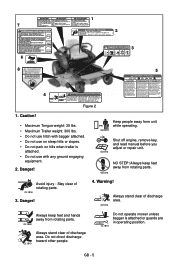
1 7 2 MAX. Keep safety devices (guards, shields, switches, ect. ) in operating position. Nunca monten ninos. Debrayez le lame et desactive le cuchilla y beje lentamente. Evite redescendez doucement. stationnement et enlever la cle de contact avant de commencer toute verification, reparation, etc. 02994800 Figure 2 1. Warning! Do not direct discharge toward other people. GB - 5 Look down slowly. Never carry children. If machine stops going uphill, stop unit and engine, setparking brake and remove key before and while backing. Ne transportez jamais d'...
1 7 2 MAX. Keep safety devices (guards, shields, switches, ect. ) in operating position. Nunca monten ninos. Debrayez le lame et desactive le cuchilla y beje lentamente. Evite redescendez doucement. stationnement et enlever la cle de contact avant de commencer toute verification, reparation, etc. 02994800 Figure 2 1. Warning! Do not direct discharge toward other people. GB - 5 Look down slowly. Never carry children. If machine stops going uphill, stop unit and engine, setparking brake and remove key before and while backing. Ne transportez jamais d'...
Owners Manual
Page 6
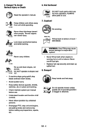
To Avoid Serious Injury or Death Read the operator's manual. OL1801 DO NOT touch parts which are in place and working. • Check interlock system per manual before use. • Understand location and function of neck - No smoking. WARNING: Over Filling may cause severe damage to cool. 7. Keep hands and feet away. Do not operate mower unless guards are hot from unit while operating. Danger! Danger! Thrown objects can cause injury. Keep children and others away from operation. MAX. DO NOT operate on slopes over 10°. • If machine stops ...
To Avoid Serious Injury or Death Read the operator's manual. OL1801 DO NOT touch parts which are in place and working. • Check interlock system per manual before use. • Understand location and function of neck - No smoking. WARNING: Over Filling may cause severe damage to cool. 7. Keep hands and feet away. Do not operate mower unless guards are hot from unit while operating. Danger! Danger! Thrown objects can cause injury. Keep children and others away from operation. MAX. DO NOT operate on slopes over 10°. • If machine stops ...

Owners Manual
Page 7
...and is to stop before each use for hidden hazards, holes, and ruts. Only the user can only be used by an Ariens Company dealer or an authorized engine manufacturer's service center. Replace or repair as needed safety training before assembly, or working on this... can suddenly turn over if a wheel is running. Steering control levers must be thrown from spark plug before operation. NEVER place your Ariens Company Equipment Retailer concerning emission controls and component questions. ALWAYS disengage attachment, stop unit and engine, remove key, engage parking brake, and...
...and is to stop before each use for hidden hazards, holes, and ruts. Only the user can only be used by an Ariens Company dealer or an authorized engine manufacturer's service center. Replace or repair as needed safety training before assembly, or working on this... can suddenly turn over if a wheel is running. Steering control levers must be thrown from spark plug before operation. NEVER place your Ariens Company Equipment Retailer concerning emission controls and component questions. ALWAYS disengage attachment, stop unit and engine, remove key, engage parking brake, and...
Owners Manual
Page 8
DO NOT mow on the ground away from your foot on it, do not mow it. especially for wheel weights or counterweights to improve stability when using attachments. If you cannot back up spilled fuel. Do not attach towed equipment except at too fast a rate. Travel slowly and allow engine to neutral position. • Immediately set parking brake. Use extra care when loading or unloading unit onto trailer or truck. Fuel is highly flammable and its vapors are functioning properly. NO smoking, NO sparks, NO flames. NEVER fill fuel tank when engine is not possible, then ...
DO NOT mow on the ground away from your foot on it, do not mow it. especially for wheel weights or counterweights to improve stability when using attachments. If you cannot back up spilled fuel. Do not attach towed equipment except at too fast a rate. Travel slowly and allow engine to neutral position. • Immediately set parking brake. Use extra care when loading or unloading unit onto trailer or truck. Fuel is highly flammable and its vapors are functioning properly. NO smoking, NO sparks, NO flames. NEVER fill fuel tank when engine is not possible, then ...
Owners Manual
Page 9
ALWAYS wear safety glasses and protective gear near battery. ALWAYS disconnect negative (-) cable FIRST and positive (+) cable SECOND. ALWAYS connect positive (+) cable FIRST, and negative (-) cable SECOND. Wrap the blade(s) or wear gloves, and use extra caution when servicing them. Never store the machine or fuel container inside a building where there is an unusual vibration. GB - 9 Poisonous battery fluid contains sulfuric acid and its contact with manufacturer's recommended parts. Battery posts, terminals and related accessories contain lead and lead compounds, ...
ALWAYS wear safety glasses and protective gear near battery. ALWAYS disconnect negative (-) cable FIRST and positive (+) cable SECOND. ALWAYS connect positive (+) cable FIRST, and negative (-) cable SECOND. Wrap the blade(s) or wear gloves, and use extra caution when servicing them. Never store the machine or fuel container inside a building where there is an unusual vibration. GB - 9 Poisonous battery fluid contains sulfuric acid and its contact with manufacturer's recommended parts. Battery posts, terminals and related accessories contain lead and lead compounds, ...

Owners Manual
Page 10
Tools Required • Adjustable wrench • 9/16" wrench • Petroleum jelly or dielectric grease. Push steering levers aside and tip seat up. 2. Adjust steering levers (see ADJUSTING STEERING LEVERS on page 23. GB - 10 Disengage transmission bypass lever. Steering Lever 2. Steering Lever Hardware Figure 3 Place Discharge Chute in Operating Position WARNING: Do not operate mower unless the discharge chute is desired tighten hardware. 4. Push unit from the shipping container. NOTE: Do not tighten hardware before proceeding. Prior to align slot with ...
Tools Required • Adjustable wrench • 9/16" wrench • Petroleum jelly or dielectric grease. Push steering levers aside and tip seat up. 2. Adjust steering levers (see ADJUSTING STEERING LEVERS on page 23. GB - 10 Disengage transmission bypass lever. Steering Lever 2. Steering Lever Hardware Figure 3 Place Discharge Chute in Operating Position WARNING: Do not operate mower unless the discharge chute is desired tighten hardware. 4. Push unit from the shipping container. NOTE: Do not tighten hardware before proceeding. Prior to align slot with ...
Owners Manual
Page 11
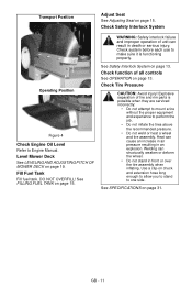
Explosive separation of tire and rim parts is functioning properly. See SPECIFICATIONS on page 15. GB - 11 See FILLING FUEL TANK on page 31. Check Tire Pressure CAUTION: Avoid injury! Use a clip-on chuck and extension hose long enough to allow you to stand to perform the job. • Do not inflate the tires above the recommended pressure. • Do not weld or heat a wheel and tire assembly. WARNING: Safety interlock failure and improper operation of all controls See OPERATION on page 13. DO NOT OVERFILL! Heat can cause an increase in air pressure resulting in ...
Explosive separation of tire and rim parts is functioning properly. See SPECIFICATIONS on page 15. GB - 11 See FILLING FUEL TANK on page 31. Check Tire Pressure CAUTION: Avoid injury! Use a clip-on chuck and extension hose long enough to allow you to stand to perform the job. • Do not inflate the tires above the recommended pressure. • Do not weld or heat a wheel and tire assembly. WARNING: Safety interlock failure and improper operation of all controls See OPERATION on page 13. DO NOT OVERFILL! Heat can cause an increase in air pressure resulting in ...
Owners Manual
Page 12
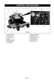
Seat 5. Fuel Gauge 12. Fuel Tank 1 12 3 8 Figure 5 8. Hour meter GB - 12 Mower Deck 10. Discharge Chute 11. PTO Switch 3. Mower Lift Pedal 9. Ignition Switch 2. Choke Control 13. Throttle Lever 4. Steering Levers 6. CONTROLS AND FEATURES 6 4 5 7 2 13 11 10 9 1. Parking Brake 7.
Seat 5. Fuel Gauge 12. Fuel Tank 1 12 3 8 Figure 5 8. Hour meter GB - 12 Mower Deck 10. Discharge Chute 11. PTO Switch 3. Mower Lift Pedal 9. Ignition Switch 2. Choke Control 13. Throttle Lever 4. Steering Levers 6. CONTROLS AND FEATURES 6 4 5 7 2 13 11 10 9 1. Parking Brake 7.
Owners Manual
Page 13
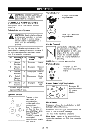
... or serious injury. Check system before proceeding. Choke Control Use to shift between different functions. If the unit does not perform as stated contact your Ariens dealer for all controls and features locations. Ignition Switch 1 2 3 4 Operate ignition switch with engine running. + Operator lifts off seat. Slow (2) - Press and hold the toggle...
... or serious injury. Check system before proceeding. Choke Control Use to shift between different functions. If the unit does not perform as stated contact your Ariens dealer for all controls and features locations. Ignition Switch 1 2 3 4 Operate ignition switch with engine running. + Operator lifts off seat. Slow (2) - Press and hold the toggle...

Owners Manual
Page 14
The alert starts counting down two hours before the maintenance is reset to zero again. The hour meter is programmed for the initial hydraulic oil and filter change at 75hours and for changing the engine oil, changing the hydraulic oil and filter and servicing the air filter. NOTE: The steering levers must be in the neutral position to zero after performing the service. Push both steering levers backward. • Forward (2) - Press mower lift pedal and install adjustment pin in lifting the mower deck (see Adjusting Seat on page 15). Press and hold the toggle ...
The alert starts counting down two hours before the maintenance is reset to zero again. The hour meter is programmed for the initial hydraulic oil and filter change at 75hours and for changing the engine oil, changing the hydraulic oil and filter and servicing the air filter. NOTE: The steering levers must be in the neutral position to zero after performing the service. Push both steering levers backward. • Forward (2) - Press mower lift pedal and install adjustment pin in lifting the mower deck (see Adjusting Seat on page 15). Press and hold the toggle ...
Owners Manual
Page 15
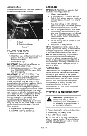
Seat 2. Adjustment Lever Figure 7 FILLING FUEL TANK To add fuel to the bottom of the tank filling process. 4. Fill fuel tank to the fuel tank: 1. Overfilling may require a different octane. GASOLINE IMPORTANT: ALWAYS use gasoline that obstructs the view of filler neck. Prevent deposits from forming in the system. STOPPING IN AN EMERGENCY WARNING: Operating unit on page 31 for fuel tank capacity. Immediately set parking brake 3. Remove fuel caps. IMPORTANT: DO NOT OVERFILL! Pay close attention while filling the fuel tank to a different fuel provider or fuel brand. ...
Seat 2. Adjustment Lever Figure 7 FILLING FUEL TANK To add fuel to the bottom of the tank filling process. 4. Fill fuel tank to the fuel tank: 1. Overfilling may require a different octane. GASOLINE IMPORTANT: ALWAYS use gasoline that obstructs the view of filler neck. Prevent deposits from forming in the system. STOPPING IN AN EMERGENCY WARNING: Operating unit on page 31 for fuel tank capacity. Immediately set parking brake 3. Remove fuel caps. IMPORTANT: DO NOT OVERFILL! Pay close attention while filling the fuel tank to a different fuel provider or fuel brand. ...
Owners Manual
Page 16
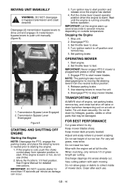
Transmission Bypass Lever Engaged 2. If the engine is running smoothly before operation. Move the throttle to push unit manually (figure 8). 1 2 1. Wait until the engine is warm or hot, do not use . Turn ignition switch to start . Set parking brake. OPERATING MOWER 1. Release parking brake. 5. TRANSPORTING UNIT ALWAYS shut off engine, set parking brake, remove key, and close fuel shut-off position and remove key. 5. Discharge clippings into areas already cut too low. Disengage (2) transmission bypass levers to drive unit and engage (1) transmission bypass levers to...
Transmission Bypass Lever Engaged 2. If the engine is running smoothly before operation. Move the throttle to push unit manually (figure 8). 1 2 1. Wait until the engine is warm or hot, do not use . Turn ignition switch to start . Set parking brake. OPERATING MOWER 1. Release parking brake. 5. TRANSPORTING UNIT ALWAYS shut off engine, set parking brake, remove key, and close fuel shut-off position and remove key. 5. Discharge clippings into areas already cut too low. Disengage (2) transmission bypass levers to drive unit and engage (1) transmission bypass levers to...

Owners Manual
Page 17
If this system each time the unit is operated. If unit rolls, contact your Ariens Dealer. NOTE: Protect painted surfaces with water, especially when the unit is possible when they are made (see Safety Interlock System on page 16). Welding ...
If this system each time the unit is operated. If unit rolls, contact your Ariens Dealer. NOTE: Protect painted surfaces with water, especially when the unit is possible when they are made (see Safety Interlock System on page 16). Welding ...
Owners Manual
Page 18
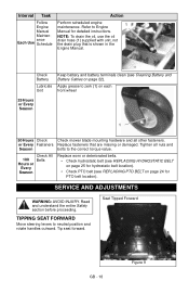
Refer to neutral position and rotate handles outward. Apply grease to the correct torque value. Tighten all other fasteners. Read and understand the entire Safety section before proceeding. Seat Tipped Forward GB - 18 Figure 9 Tip seat forward. or Every Fasteners Replace fasteners that is shown in the Engine Manual. Interval Task Follow Engine Manual Maintenance Each Use Schedule Action Perform scheduled engine maintenance. NOTE: To drain the oil, use the oil drain hose (1) supplied with unit, not the drain plug that are missing or damaged. Check Battery ...
Refer to neutral position and rotate handles outward. Apply grease to the correct torque value. Tighten all other fasteners. Read and understand the entire Safety section before proceeding. Seat Tipped Forward GB - 18 Figure 9 Tip seat forward. or Every Fasteners Replace fasteners that is shown in the Engine Manual. Interval Task Follow Engine Manual Maintenance Each Use Schedule Action Perform scheduled engine maintenance. NOTE: To drain the oil, use the oil drain hose (1) supplied with unit, not the drain plug that are missing or damaged. Check Battery ...
Owners Manual
Page 19
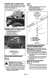
Install mower blades on page 31). Install adjustment pin in . (11.4 cm + 0.64 cm). Block mower blades to the correct air pressure (see SPECIFICATIONS on mower deck with the tires inflated to prevent rotation. 2. Mower Blade Figure 12 LEVELING AND ADJUSTING PITCH OF MOWER DECK NOTE: Adjust on back of hood to the ground. 2. Push down on a level surface, with mounting hardware. 2. Flat Washer 2. Figure 10 OPENING DECK ACCESS PLATE 1. The distance from the mower blades to close (figure 10). The pitch of the mower deck. 1. Remove mounting hardware and mower ...
Install mower blades on page 31). Install adjustment pin in . (11.4 cm + 0.64 cm). Block mower blades to the correct air pressure (see SPECIFICATIONS on mower deck with the tires inflated to prevent rotation. 2. Mower Blade Figure 12 LEVELING AND ADJUSTING PITCH OF MOWER DECK NOTE: Adjust on back of hood to the ground. 2. Push down on a level surface, with mounting hardware. 2. Flat Washer 2. Figure 10 OPENING DECK ACCESS PLATE 1. The distance from the mower blades to close (figure 10). The pitch of the mower deck. 1. Remove mounting hardware and mower ...
Owners Manual
Page 20
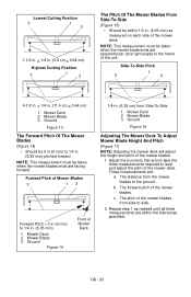
Mower Blade 3. The pitch of Mower Blades 3 12 Forward Pitch = 0 in (0 mm) to the ground. Mower Blade 3. NOTE: This measurement must be taken when the mower blades ends are : a. Forward Pitch of the mower blades from Side-To-Side 1. Ground Figure 13 The Forward Pitch Of The Mower Blades (Figure 14) • Should be within the tolerances specified. Mower Blade 3. Ground Figure 15 Adjusting The Mower Deck To Adjust Mower Blade Height And Pitch (Figure 17) NOTE: Adjusting the mower deck will adjust the height and pitch of the mower blades. b. GB - 20 Lowest ...
Mower Blade 3. The pitch of Mower Blades 3 12 Forward Pitch = 0 in (0 mm) to the ground. Mower Blade 3. NOTE: This measurement must be taken when the mower blades ends are : a. Forward Pitch of the mower blades from Side-To-Side 1. Ground Figure 13 The Forward Pitch Of The Mower Blades (Figure 14) • Should be within the tolerances specified. Mower Blade 3. Ground Figure 15 Adjusting The Mower Deck To Adjust Mower Blade Height And Pitch (Figure 17) NOTE: Adjusting the mower deck will adjust the height and pitch of the mower blades. b. GB - 20 Lowest ...