

AP1710-S5 English Manual
Page 2
ASUS provides this manual ae furnished for informational use or data, interruption of business and the like), even if ASUS has been advised of the possibility of such damages arising from any defect or error in this manual may or may be construed as is authorized in writing by ASUS; or (2) the serial number of this manual, including the products and software described...
ASUS provides this manual ae furnished for informational use or data, interruption of business and the like), even if ASUS has been advised of the possibility of such damages arising from any defect or error in this manual may or may be construed as is authorized in writing by ASUS; or (2) the serial number of this manual, including the products and software described...
AP1710-S5 English Manual
Page 3
...1.6 LED information 1-7 Chapter 2: Hardware setup 2-1 2.1 Chassis cover 2-2 2.1.1 Removing the cover 2-2 2.1.2 Installing the cover 2-2 2.2 Motherboard information 2-3 2.3 Central Processing Unit (CPU 2-4 2.3.1 Installing the CPU 2-5 2.3.2 Installing the heatsink and fan 2-6 2.4 System memory 2-8 2.4.1 Memory configurations 2-9 2.4.2 Installing a DIMM 2-10 2.4.3 Removing a DIMM 2-10 2.5 5.25-inch drives 2-11 2.5.1 Removing the front panel assembly 2-11 2.5.2 Installing a 5.25-inch drive 2-12 2.6 Hard disk drives 2-16 2.6.1 Installing a hard disk drive 2-16 2.7 Expansion cards...
...1.6 LED information 1-7 Chapter 2: Hardware setup 2-1 2.1 Chassis cover 2-2 2.1.1 Removing the cover 2-2 2.1.2 Installing the cover 2-2 2.2 Motherboard information 2-3 2.3 Central Processing Unit (CPU 2-4 2.3.1 Installing the CPU 2-5 2.3.2 Installing the heatsink and fan 2-6 2.4 System memory 2-8 2.4.1 Memory configurations 2-9 2.4.2 Installing a DIMM 2-10 2.4.3 Removing a DIMM 2-10 2.5 5.25-inch drives 2-11 2.5.1 Removing the front panel assembly 2-11 2.5.2 Installing a 5.25-inch drive 2-12 2.6 Hard disk drives 2-16 2.6.1 Installing a hard disk drive 2-16 2.7 Expansion cards...
AP1710-S5 English Manual
Page 5
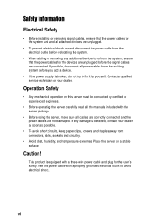
... from digital apparatus set out in a residential installation. However, there is required to radio communications. The use of the FCC Rules. v Canadian Department of the following two conditions: • This device may cause undesired operation. This equipment has been tested and found to comply with FCC regulations. WARNING! This class B digital apparatus complies with FCC Rules Part 15. These...
... from digital apparatus set out in a residential installation. However, there is required to radio communications. The use of the FCC Rules. v Canadian Department of the following two conditions: • This device may cause undesired operation. This equipment has been tested and found to comply with FCC regulations. WARNING! This class B digital apparatus complies with FCC Rules Part 15. These...
AP1710-S5 English Manual
Page 6
... from connectors, slots, sockets and circuitry. • Avoid dust, humidity, and temperature extremes. Caution! Use the power cable with a three-wire power cable and plug for the devices are unplugged before the signal cables are unplugged. • To prevent electrical shock hazard, disconnect the power cable from the electrical outlet before you add a device. • If the power supply is detected, contact your dealer. Contact a qualified service technician...
... from connectors, slots, sockets and circuitry. • Avoid dust, humidity, and temperature extremes. Caution! Use the power cable with a three-wire power cable and plug for the devices are unplugged before the signal cables are unplugged. • To prevent electrical shock hazard, disconnect the power cable from the electrical outlet before you add a device. • If the power supply is detected, contact your dealer. Contact a qualified service technician...
AP1710-S5 English Manual
Page 8
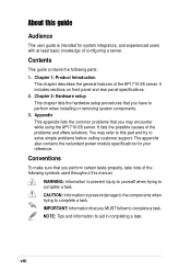
... guide contains the following symbols used throughout this part and try to complete a task. Chapter 2: Hardware setup This chapter lists the hardware setup procedures that you have to complete a task. You may encounter while using the AP1710-S5 server. IMPORTANT: Information that you MUST follow to perform when installing or removing system components. 3. The appendix also contains the redundant power module specifications for system integrators, and experienced users...
... guide contains the following symbols used throughout this part and try to complete a task. Chapter 2: Hardware setup This chapter lists the hardware setup procedures that you have to complete a task. You may encounter while using the AP1710-S5 server. IMPORTANT: Information that you MUST follow to perform when installing or removing system components. 3. The appendix also contains the redundant power module specifications for system integrators, and experienced users...

AP1710-S5 English Manual
Page 12
... Tower/5U Rackmount chassis including: • ASUS PRL-DL motherboard • 500W redundant power supply with single power module • BP6LS-AS 35 SCSI backplane board • CD-ROM drive • floppy disk drive • chassis fan • hot-swap SCSI hard disk drive trays (6 units) • chassis roller wheels (4 sets) • special CPU heatsink and fan assembly (2 sets) 2. Keys (2 pieces) 6. ASUS PXL-S30 Ultra320 dual-channel SCSI RAID card 3. System screws and labels 5. 1.1 System package contents Check your ASUS AP1710-S5 package for the...
... Tower/5U Rackmount chassis including: • ASUS PRL-DL motherboard • 500W redundant power supply with single power module • BP6LS-AS 35 SCSI backplane board • CD-ROM drive • floppy disk drive • chassis fan • hot-swap SCSI hard disk drive trays (6 units) • chassis roller wheels (4 sets) • special CPU heatsink and fan assembly (2 sets) 2. Keys (2 pieces) 6. ASUS PXL-S30 Ultra320 dual-channel SCSI RAID card 3. System screws and labels 5. 1.1 System package contents Check your ASUS AP1710-S5 package for the...

AP1710-S5 English Manual
Page 13
... DDR DIMMs for 80-pin SCH2 SCSI hard drives Management ASUS System Monitoring Agent (ASMA) ASUS Server Web-based Management (ASWM) Hardware Monitors Voltage, temperature, and fan speed monitoring Automatic System Restart (ASR) feature Power Supply 500W redundant power supply ASUS AP1710-S5 user guide 1-3 1.2 System specifications The ASUS AP1710-S5 server is a stylish server system featuring the ASUS PRL-DL motherboard. The server supports the Intel® Xeon™ processor in rear panel), RJ-45 LAN port and 2 x 68-pin SCSI connectors Expansion Slots 4 x 64-bit/33Mhz 3V PCI slot...
... DDR DIMMs for 80-pin SCH2 SCSI hard drives Management ASUS System Monitoring Agent (ASMA) ASUS Server Web-based Management (ASWM) Hardware Monitors Voltage, temperature, and fan speed monitoring Automatic System Restart (ASR) feature Power Supply 500W redundant power supply ASUS AP1710-S5 user guide 1-3 1.2 System specifications The ASUS AP1710-S5 server is a stylish server system featuring the ASUS PRL-DL motherboard. The server supports the Intel® Xeon™ processor in rear panel), RJ-45 LAN port and 2 x 68-pin SCSI connectors Expansion Slots 4 x 64-bit/33Mhz 3V PCI slot...
AP1710-S5 English Manual
Page 14
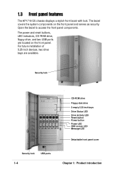
... Drive Status LED Drive Activity LED Reset button Power button Power LED HDD access LED Message LED Detachable front panel cover Security lock USB ports 1-4 Chapter 1: Product introduction The bezel covers the system components on the front panel. The power and reset buttons, LED indicators, CD-ROM drive, floppy drive, and two USB ports are available. For future installation of 5.25-inch devices, two drive bays are located on the front panel and serves as security. Open the bezel to access the front panel components. 1.3 Front panel features The AP1710-S5 chassis displays...
... Drive Status LED Drive Activity LED Reset button Power button Power LED HDD access LED Message LED Detachable front panel cover Security lock USB ports 1-4 Chapter 1: Product introduction The bezel covers the system components on the front panel. The power and reset buttons, LED indicators, CD-ROM drive, floppy drive, and two USB ports are available. For future installation of 5.25-inch devices, two drive bays are located on the front panel and serves as security. Open the bezel to access the front panel components. 1.3 Front panel features The AP1710-S5 chassis displays...

AP1710-S5 English Manual
Page 15
1.4. Rear panel features The rear panel includes a slot for the motherboard rear I/O ports, six full-length expansion slots, a chassis lock and intrusion switch, a vent for the system fan, and redundant power supply modules. Power supply modules P/S2 mouse port P/S2 keyboard port USB ports Serial port Parallel port VGA port Gigabit LAN port Gigabit LAN card (optional) SCSI card (optional AC IN connector AC Power status LED 12cm fan vent Chassis lock Expansion slots ASUS AP1710-S5 user guide 1-5
1.4. Rear panel features The rear panel includes a slot for the motherboard rear I/O ports, six full-length expansion slots, a chassis lock and intrusion switch, a vent for the system fan, and redundant power supply modules. Power supply modules P/S2 mouse port P/S2 keyboard port USB ports Serial port Parallel port VGA port Gigabit LAN port Gigabit LAN card (optional) SCSI card (optional AC IN connector AC Power status LED 12cm fan vent Chassis lock Expansion slots ASUS AP1710-S5 user guide 1-5
AP1710-S5 English Manual
Page 17
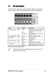
ASUS AP1710-S5 user guide 1-7 no incoming event ASMS indicates a HW monitor event The Power, HDD Access and Message LEDs are visible even if the system front bezel is normal; ON Blinking OFF Blinking OFF Blinking *SCSI Access Fault-Tolerant Enclosure Description Bridge board connected to the picture for the LED location and the following table for the LED status description ! Refer to backplane Installed HDD is in good condition HDD failure HDD rebuilding using the RAID card SAF-TE* function...
ASUS AP1710-S5 user guide 1-7 no incoming event ASMS indicates a HW monitor event The Power, HDD Access and Message LEDs are visible even if the system front bezel is normal; ON Blinking OFF Blinking OFF Blinking *SCSI Access Fault-Tolerant Enclosure Description Bridge board connected to the picture for the LED location and the following table for the LED status description ! Refer to backplane Installed HDD is in good condition HDD failure HDD rebuilding using the RAID card SAF-TE* function...

AP1710-S5 English Manual
Page 19
Chapter 2 This chapter lists the hardware setup procedures that you have to perform when installing or removing system components. Hardware setup ASUS AP1710-S5 user guide 2-1
Chapter 2 This chapter lists the hardware setup procedures that you have to perform when installing or removing system components. Hardware setup ASUS AP1710-S5 user guide 2-1
AP1710-S5 English Manual
Page 21
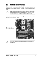
.... 2.2 Motherboard information The AP1710-S5 comes with the ASUS PRL-DL motherboard that uses the extended ATX form factor measuring 12 inches x 10.5 inches (30.5 x 26.67 cm). This side towards the rear of the chassis Refer to unplug the power cord before installing or removing any motherboard component or connection. Failure to do so may cause you physical injury and may damage motherboard components. ASUS AP1710-S5 user guide 2-3
.... 2.2 Motherboard information The AP1710-S5 comes with the ASUS PRL-DL motherboard that uses the extended ATX form factor measuring 12 inches x 10.5 inches (30.5 x 26.67 cm). This side towards the rear of the chassis Refer to unplug the power cord before installing or removing any motherboard component or connection. Failure to do so may cause you physical injury and may damage motherboard components. ASUS AP1710-S5 user guide 2-3
AP1710-S5 English Manual
Page 25
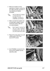
... the fan power cable are connected properly. Make sure that the heatsink and fan assembly is slotted so it . 4. Repeat the same steps if you fail to connect the CPU fan cable. The fan cable plug is stable in place, connect the fan cable to the fan connector on the motherboard labeled CPUFAN1. Don't forget to plug the fan cable. 5. Hardware monitoring errors may occur if you will install another CPU in one orientation. ASUS AP1710-S5 user guide 2-7 Use CPUFAN2 connector for...
... the fan power cable are connected properly. Make sure that the heatsink and fan assembly is slotted so it . 4. Repeat the same steps if you fail to connect the CPU fan cable. The fan cable plug is stable in place, connect the fan cable to the fan connector on the motherboard labeled CPUFAN1. Don't forget to plug the fan cable. 5. Hardware monitoring errors may occur if you will install another CPU in one orientation. ASUS AP1710-S5 user guide 2-7 Use CPUFAN2 connector for...
AP1710-S5 English Manual
Page 29
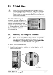
... remove the front panel assembly (front bezel and front panel cover). The two lower bays (labeled 2 and 3) are located on the left side of the chassis. The front panel assembly is attached to the chassis through four hooked tabs on the upper front part of the front panel. 1 ASUS AP1710-S5 user guide Hooked tab 2-11 A CD-ROM drive that it may cause severe damage to the motherboard...
... remove the front panel assembly (front bezel and front panel cover). The two lower bays (labeled 2 and 3) are located on the left side of the chassis. The front panel assembly is attached to the chassis through four hooked tabs on the upper front part of the front panel. 1 ASUS AP1710-S5 user guide Hooked tab 2-11 A CD-ROM drive that it may cause severe damage to the motherboard...

AP1710-S5 English Manual
Page 38
... of the chassis (under the backplane board) to keep the expansion cards firmly seated on the card guide. Plastic long-card support To install a long expansion card: 1. Screwless lock 2-20 Chapter 2: Hardware setup Position the expansion card above the PCI slot that correspond to use the plastic card support located near the front of the card to the expansion slot on the slot. 4. This card support has individual card guides that you are installing a long expansion card, such as some types of RAID cards, use . 2. Slide in...
... of the chassis (under the backplane board) to keep the expansion cards firmly seated on the card guide. Plastic long-card support To install a long expansion card: 1. Screwless lock 2-20 Chapter 2: Hardware setup Position the expansion card above the PCI slot that correspond to use the plastic card support located near the front of the card to the expansion slot on the slot. 4. This card support has individual card guides that you are installing a long expansion card, such as some types of RAID cards, use . 2. Slide in...
AP1710-S5 English Manual
Page 40
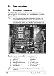
... devices that all cables are already connected upon shipment. Secondary IDE 8. Most of the cables for the chassis kit are routed properly for detailed information on the connectors. 2-22 Chapter 2: Hardware setup SMBus panel to the motherboard 1. HDD cable 10. 24-pin ATX power 11. 8-pin 12V AUX power 12. SCSI controller Refer to the motheboard user guide for better system stability and performance. Front USB connector 6. 2.8 Cable connections 2.8.1 Motherboard connections The AP1710-S5 chassis includes the power...
... devices that all cables are already connected upon shipment. Secondary IDE 8. Most of the cables for the chassis kit are routed properly for detailed information on the connectors. 2-22 Chapter 2: Hardware setup SMBus panel to the motherboard 1. HDD cable 10. 24-pin ATX power 11. 8-pin 12V AUX power 12. SCSI controller Refer to the motheboard user guide for better system stability and performance. Front USB connector 6. 2.8 Cable connections 2.8.1 Motherboard connections The AP1710-S5 chassis includes the power...

AP1710-S5 English Manual
Page 41
... or removal of SCSI hard disks. The LED connectors on the motherboard) HDD status LEDs HDD activity LEDs 2-23 The backplane design incorporates a hot-swap feature to support SCA SCSI hard disks. Front side Fan connectors Power connectors (connects power plugs from the power supply) SMBus connector (connects the 6-pin plug from the power supply) Back side SCSI ID = 0 Disk drive 1 SCSI ID = 1 Disk drive 2 SCSI ID = 2 Disk drive 3 SCSI ID = 3 Disk drive 4 SCSI ID = 4 Disk drive 5 SCSI ID = 5 Disk drive 6 ASUS AP1710-S5 user guide 68-pin SCSI connector (connect to the SCSI connector on...
... or removal of SCSI hard disks. The LED connectors on the motherboard) HDD status LEDs HDD activity LEDs 2-23 The backplane design incorporates a hot-swap feature to support SCA SCSI hard disks. Front side Fan connectors Power connectors (connects power plugs from the power supply) SMBus connector (connects the 6-pin plug from the power supply) Back side SCSI ID = 0 Disk drive 1 SCSI ID = 1 Disk drive 2 SCSI ID = 2 Disk drive 3 SCSI ID = 3 Disk drive 4 SCSI ID = 4 Disk drive 5 SCSI ID = 5 Disk drive 6 ASUS AP1710-S5 user guide 68-pin SCSI connector (connect to the SCSI connector on...

AP1710-S5 English Manual
Page 43
... components: 1. ASUS AP1710-S5 user guide 2-25 This section describes how to push the pin locks on the motherboard. 2. Chassis fan 2. 2.9 Removable components You may need to remove previously installed components when installing or removing system devices. HDD blower 3. Power supply modules 5. Pull out the pin locks from the inside of the chassis. Floppy disk drive 4. Disconnect the 3-pin fan cable from the connector on the four corners of the fan from the rear panel. 4. Pin...
... components: 1. ASUS AP1710-S5 user guide 2-25 This section describes how to push the pin locks on the motherboard. 2. Chassis fan 2. 2.9 Removable components You may need to remove previously installed components when installing or removing system devices. HDD blower 3. Power supply modules 5. Pull out the pin locks from the inside of the chassis. Floppy disk drive 4. Disconnect the 3-pin fan cable from the connector on the four corners of the fan from the rear panel. 4. Pin...
AP1710-S5 English Manual
Page 45
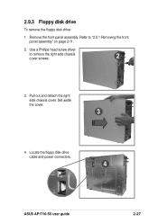
Remove the front panel assembly. 2.9.3 Floppy disk drive To remove the floppy disk drive: 1. Locate the floppy disk drive cable and power connectors. 4 ASUS AP1710-S5 user guide 2-27 Set aside the cover. 3 4. Refer to remove the right side chassis cover screws. 2 3. Pull out and detach the right side chassis cover. Use a Phillips head screw driver to "2.5.1 Removing the front panel assembly" on page 2-11. 2.
Remove the front panel assembly. 2.9.3 Floppy disk drive To remove the floppy disk drive: 1. Locate the floppy disk drive cable and power connectors. 4 ASUS AP1710-S5 user guide 2-27 Set aside the cover. 3 4. Refer to remove the right side chassis cover screws. 2 3. Pull out and detach the right side chassis cover. Use a Phillips head screw driver to "2.5.1 Removing the front panel assembly" on page 2-11. 2.

AP1710-S5 English Manual
Page 53
... memory modules and make sure that the DIMMs are properly installed on 1. Make sure that the cables are properly installed. On SCSI models, make sure you have installed the LAN drivers from the support CD. Network connection not available 1. Check if it was turned on the sockets. 3. Check if a bootable HDD is connected to the SCSI connectors on the rear panel. 2. The message "Non-system disk or disk error" appears 1. Make sure that the network cable is active. 2. ASUS AP1710-S5 user guide...
... memory modules and make sure that the DIMMs are properly installed on 1. Make sure that the cables are properly installed. On SCSI models, make sure you have installed the LAN drivers from the support CD. Network connection not available 1. Check if it was turned on the sockets. 3. Check if a bootable HDD is connected to the SCSI connectors on the rear panel. 2. The message "Non-system disk or disk error" appears 1. Make sure that the network cable is active. 2. ASUS AP1710-S5 user guide...


