
AT3IONT-I Series user's manual
Page 1
Motherboard AT3IONT-I DELUXE AT3IONT-I
Motherboard AT3IONT-I DELUXE AT3IONT-I

AT3IONT-I Series user's manual
Page 2
...FOR INFORMATIONAL USE ONLY, AND ARE SUBJECT TO CHANGE AT ANY TIME WITHOUT NOTICE, AND SHOULD NOT BE CONSTRUED AS A COMMITMENT BY ASUS. ASUS ASSUMES NO RESPONSIBILITY OR LIABILITY FOR ANY ERRORS OR INACCURACIES THAT MAY APPEAR IN THIS MANUAL, INCLUDING THE PRODUCTS AND SOFTWARE DESCRIBED IN IT...Beitou, Taipei 112 Taiwan In your contact details so that is valid to the owners' benefit, without any means, except documentation kept by ASUS; ASUS PROVIDES THIS MANUAL "AS IS" WITHOUT WARRANTY OF ANY KIND, EITHER EXPRESS OR IMPLIED, INCLUDING BUT NOT LIMITED TO THE IMPLIED WARRANTIES OR...
...FOR INFORMATIONAL USE ONLY, AND ARE SUBJECT TO CHANGE AT ANY TIME WITHOUT NOTICE, AND SHOULD NOT BE CONSTRUED AS A COMMITMENT BY ASUS. ASUS ASSUMES NO RESPONSIBILITY OR LIABILITY FOR ANY ERRORS OR INACCURACIES THAT MAY APPEAR IN THIS MANUAL, INCLUDING THE PRODUCTS AND SOFTWARE DESCRIBED IN IT...Beitou, Taipei 112 Taiwan In your contact details so that is valid to the owners' benefit, without any means, except documentation kept by ASUS; ASUS PROVIDES THIS MANUAL "AS IS" WITHOUT WARRANTY OF ANY KIND, EITHER EXPRESS OR IMPLIED, INCLUDING BUT NOT LIMITED TO THE IMPLIED WARRANTIES OR...

AT3IONT-I Series user's manual
Page 3
Contents Notices...v Safety information vi About this guide vi AT3IONT-I Series specifications summary viii Chapter 1: Product introduction 1.1 Before you proceed 1-1 1.2 Motherboard overview 1-2 1.2.1 Motherboard layout 1-2 1.2.2 Layout contents 1-2 1.3 Central Processing Unit (CPU ... 1-8 1.7.1 Rear panel connectors 1-8 1.7.2 Internal connectors 1-11 1.8 Software support 1-16 1.8.1 Installing an operating system 1-16 1.8.2 Support DVD information 1-16 1.8.3 ASUS VideoSecurity 1-17 1.8.4 ASUS Home Theater Gate 1-19 Chapter 2: BIOS information 2.1 Managing and updating your BIOS...
Contents Notices...v Safety information vi About this guide vi AT3IONT-I Series specifications summary viii Chapter 1: Product introduction 1.1 Before you proceed 1-1 1.2 Motherboard overview 1-2 1.2.1 Motherboard layout 1-2 1.2.2 Layout contents 1-2 1.3 Central Processing Unit (CPU ... 1-8 1.7.1 Rear panel connectors 1-8 1.7.2 Internal connectors 1-11 1.8 Software support 1-16 1.8.1 Installing an operating system 1-16 1.8.2 Support DVD information 1-16 1.8.3 ASUS VideoSecurity 1-17 1.8.4 ASUS Home Theater Gate 1-19 Chapter 2: BIOS information 2.1 Managing and updating your BIOS...

AT3IONT-I Series user's manual
Page 4
... EuP [Disabled 2-12 2.5.5 APM Configuration 2-12 2.5.6 Hardware Monitor 2-12 2.6 Boot menu 2-13 2.6.1 Boot Device Priority 2-13 2.6.2 Boot Settings Configuration 2-13 2.6.3 Security 2-14 2.7 Tools menu 2-15 2.7.1 ASUS EZ Flash 2 2-15 2.7.2 Express Gate [Auto 2-16 2.7.3 AI NET 2 2-16 2.8 Exit menu 2-16 iv
... EuP [Disabled 2-12 2.5.5 APM Configuration 2-12 2.5.6 Hardware Monitor 2-12 2.6 Boot menu 2-13 2.6.1 Boot Device Priority 2-13 2.6.2 Boot Settings Configuration 2-13 2.6.3 Security 2-14 2.7 Tools menu 2-15 2.7.1 ASUS EZ Flash 2 2-15 2.7.2 Express Gate [Auto 2-16 2.7.3 AI NET 2 2-16 2.8 Exit menu 2-16 iv

AT3IONT-I Series user's manual
Page 5
... parts and recycling. Changes or modifications to which can radiate radio frequency energy and, if not installed and used in our products at ASUS REACH website at http://csr.asus.com/english/REACH.htm. Canadian Department of the following two conditions: • This device may not cause harmful interference, and • This...
... parts and recycling. Changes or modifications to which can radiate radio frequency energy and, if not installed and used in our products at ASUS REACH website at http://csr.asus.com/english/REACH.htm. Canadian Department of the following two conditions: • This device may not cause harmful interference, and • This...

AT3IONT-I Series user's manual
Page 6
How this guide This user guide contains the information you are using, contact your local power company. • If the power supply is broken, do not try to fix it may become wet. • Place the product on it supports. • Chapter 2: BIOS information This chapter tells how to change system settings through the BIOS Setup menus. These devices could interrupt the grounding circuit. • Ensure that your power supply is organized This guide contains the following parts: • Chapter 1: Product introduction This chapter describes the features of the BIOS parameters are ...
How this guide This user guide contains the information you are using, contact your local power company. • If the power supply is broken, do not try to fix it may become wet. • Place the product on it supports. • Chapter 2: BIOS information This chapter tells how to change system settings through the BIOS Setup menus. These devices could interrupt the grounding circuit. • Ensure that your power supply is organized This guide contains the following parts: • Chapter 1: Product introduction This chapter describes the features of the BIOS parameters are ...

AT3IONT-I Series user's manual
Page 7
...follow to emphasize a word or a phrase. Example: ++ vii IMPORTANT: Instructions that you must press two or more information Refer to the ASUS contact information. 2. These documents are linked with a plus sign (+). Keys enclosed in this manual. Refer to the following symbols used in ... package may include optional documentation, such as warranty flyers, that may have been added by your dealer. ASUS websites The ASUS website provides updated information on ASUS hardware and software products. CAUTION: Information to prevent damage to the components when trying to help you must...
...follow to emphasize a word or a phrase. Example: ++ vii IMPORTANT: Instructions that you must press two or more information Refer to the ASUS contact information. 2. These documents are linked with a plus sign (+). Keys enclosed in this manual. Refer to the following symbols used in ... package may include optional documentation, such as warranty flyers, that may have been added by your dealer. ASUS websites The ASUS website provides updated information on ASUS hardware and software products. CAUTION: Information to prevent damage to the components when trying to help you must...

AT3IONT-I Series user's manual
Page 8
... in the front panel to 1920 x 1536 x 32 Bpp @75Hz Supports HDMI with max. AT3IONT-I Series specifications summary CPU Chipset Front Side Bus Memory Graphics Expansion slot Storage Audio LAN USB ASUS special features Integrated Dual-Core Intel® Atom™ 330 processor NVIDIA® ION™ ...-ECC 1066/800 MHz DDR3 memory modules * Refer to 10 USB 2.0/1.1 ports (4 ports at mid-board, 6 ports at back panel) ASUS CrashFree BIOS 3 ASUS EZ Flash 2 ASUS MyLogo 2™ ASUS AI NET 2 ASUS Express Gate Home Theater Gate ASUS Q-Fan Stack Cool3+ (continued on the next page) viii
... in the front panel to 1920 x 1536 x 32 Bpp @75Hz Supports HDMI with max. AT3IONT-I Series specifications summary CPU Chipset Front Side Bus Memory Graphics Expansion slot Storage Audio LAN USB ASUS special features Integrated Dual-Core Intel® Atom™ 330 processor NVIDIA® ION™ ...-ECC 1066/800 MHz DDR3 memory modules * Refer to 10 USB 2.0/1.1 ports (4 ports at mid-board, 6 ports at back panel) ASUS CrashFree BIOS 3 ASUS EZ Flash 2 ASUS MyLogo 2™ ASUS AI NET 2 ASUS Express Gate Home Theater Gate ASUS Q-Fan Stack Cool3+ (continued on the next page) viii

AT3IONT-I Series user's manual
Page 9
...(RJ-45) port 6 x USB 2.0/1.1 ports 3 x Audio jacks 1 x DC port* 1 x Bluetooth adapter* 1 x WLAN antenna port* 2 x RCA out ports* * For AT3IONT-I DELUXE only 2 x USB 2.0/1.1 connector supports additional 4 USB 2.0/1.1 ports 1 x CPU fan connector 1 x Chassis fan connector 1 x Power fan connector 4 x Serial ATA connectors 1 ... cable* 1 x Remote Controller* 1 x Receiver* 1 x WiFi antenna* 1 x 90W DC adapter* 1 x Power cord* * For AT3IONT-I DELUXE only Drivers ASUS PC Probe II ASUS Update Anti-virus software (OEM version) Mini ITX form factor: 6.75 in x 6.75 in (17.1cm x 17.1cm) *Specifications are ...
...(RJ-45) port 6 x USB 2.0/1.1 ports 3 x Audio jacks 1 x DC port* 1 x Bluetooth adapter* 1 x WLAN antenna port* 2 x RCA out ports* * For AT3IONT-I DELUXE only 2 x USB 2.0/1.1 connector supports additional 4 USB 2.0/1.1 ports 1 x CPU fan connector 1 x Chassis fan connector 1 x Power fan connector 4 x Serial ATA connectors 1 ... cable* 1 x Remote Controller* 1 x Receiver* 1 x WiFi antenna* 1 x 90W DC adapter* 1 x Power cord* * For AT3IONT-I DELUXE only Drivers ASUS PC Probe II ASUS Update Anti-virus software (OEM version) Mini ITX form factor: 6.75 in x 6.75 in (17.1cm x 17.1cm) *Specifications are ...

AT3IONT-I Series user's manual
Page 10
... your motherboard package. The illustration below shows the location of accessories. • AT3IONT-I Series motherboards include AT3IONT-I and AT3IONT-I DELUXE two models. Refer to page ix for buying an ASUS® AT3IONT-I SERIES Onboard LED 1-1 Chapter 1: Product introduction Onboard LED The motherboard comes with... the system is a reminder that lights up to the motherboard, peripherals, or components. SB_PWR AT3IONT-I DELUXE ON OFF Standby Power Powered Off AT3IONT-I Series motherboard! Before you must shut down the system and unplug the power cable before you...
... your motherboard package. The illustration below shows the location of accessories. • AT3IONT-I Series motherboards include AT3IONT-I and AT3IONT-I DELUXE two models. Refer to page ix for buying an ASUS® AT3IONT-I SERIES Onboard LED 1-1 Chapter 1: Product introduction Onboard LED The motherboard comes with... the system is a reminder that lights up to the motherboard, peripherals, or components. SB_PWR AT3IONT-I DELUXE ON OFF Standby Power Powered Off AT3IONT-I Series motherboard! Before you must shut down the system and unplug the power cable before you...

AT3IONT-I Series user's manual
Page 11
... rear part of the chassis. Serial port connectors (10-1 pin COM1) 3. 1.2 1.2.1 Motherboard overview Motherboard layout ASUS AT3IONT-I Series motherboards include AT3IONT-I and AT3IONT-I DELUXE Lithium Cell CMOS Power DDR3 DIMM_A1 (64bit, 240-pin module) BT_USB34 LAN1_USB12 RCA_OUT AUDIO RTL 8112L AAFP ...-1 pin AAFP) USB connector (10-1 pin USB78, USB910) Page 1-14 1-8 1-1 1-11 1-13 1-12 ASUS AT3IONT-I /O 5 CPU_FAN Intel® HDMI VGA Place this user guide are for AT3IONT-I DELUXE only. CPU, power, and chassis fan connectors (3-pin CPU_FAN, 3-pin PWR_FAN, 3-pin CHA_FAN) 2. ...
... rear part of the chassis. Serial port connectors (10-1 pin COM1) 3. 1.2 1.2.1 Motherboard overview Motherboard layout ASUS AT3IONT-I Series motherboards include AT3IONT-I and AT3IONT-I DELUXE Lithium Cell CMOS Power DDR3 DIMM_A1 (64bit, 240-pin module) BT_USB34 LAN1_USB12 RCA_OUT AUDIO RTL 8112L AAFP ...-1 pin AAFP) USB connector (10-1 pin USB78, USB910) Page 1-14 1-8 1-1 1-11 1-13 1-12 ASUS AT3IONT-I /O 5 CPU_FAN Intel® HDMI VGA Place this user guide are for AT3IONT-I DELUXE only. CPU, power, and chassis fan connectors (3-pin CPU_FAN, 3-pin PWR_FAN, 3-pin CHA_FAN) 2. ...

AT3IONT-I Series user's manual
Page 12
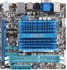
The figure illustrates the location of the DDR3 DIMM sockets: AT3IONT-I DELUXE DIMM_B1 DIMM_A1 Channel Channel A Channel B Sockets DIMM_A1 DIMM_B1 AT3IONT-I SERIES 240-pin DDR3 DIMM sockets 1-3 Chapter 1: Product introduction Intel® Atom330 AT3IONT-I SERIES CPU 1.4 System memory 1.4.1 Overview The motherboard comes with an onboard Dual-Core Intel® Atom™ 330 processor and a specially designed CPU heatsink. AT3IONT-I DELUXE 1.3 Central Processing Unit (CPU) The motherboard comes with two Double Data Rate 3 (DDR3) Dual Inline Memory Modules (DIMM) sockets.
The figure illustrates the location of the DDR3 DIMM sockets: AT3IONT-I DELUXE DIMM_B1 DIMM_A1 Channel Channel A Channel B Sockets DIMM_A1 DIMM_B1 AT3IONT-I SERIES 240-pin DDR3 DIMM sockets 1-3 Chapter 1: Product introduction Intel® Atom330 AT3IONT-I SERIES CPU 1.4 System memory 1.4.1 Overview The motherboard comes with an onboard Dual-Core Intel® Atom™ 330 processor and a specially designed CPU heatsink. AT3IONT-I DELUXE 1.3 Central Processing Unit (CPU) The motherboard comes with two Double Data Rate 3 (DDR3) Dual Inline Memory Modules (DIMM) sockets.

AT3IONT-I Series user's manual
Page 13
..., the actual usable memory for the single-channel operation. • Always install DIMMs with the same CAS latency. AT3IONT-I Series 1-4 Size SS/ DS Brand Chip No. Crucial CT25664BA1067.16FF 2048MB DS ELPIDA EBJ10UE8EDF0-AE-F 1024MB SS ELPIDA...; - •• - •• - •• 1.5V •• - •• - •• - •• - •• ASUS AT3IONT-I Series Motherboard Qualified Vendors Lists (QVL) DDR3-1067 MHz capability Vendor Part No. For optimum compatibility, it is then mapped for the OS can be...
..., the actual usable memory for the single-channel operation. • Always install DIMMs with the same CAS latency. AT3IONT-I Series 1-4 Size SS/ DS Brand Chip No. Crucial CT25664BA1067.16FF 2048MB DS ELPIDA EBJ10UE8EDF0-AE-F 1024MB SS ELPIDA...; - •• - •• - •• 1.5V •• - •• - •• - •• - •• ASUS AT3IONT-I Series Motherboard Qualified Vendors Lists (QVL) DDR3-1067 MHz capability Vendor Part No. For optimum compatibility, it is then mapped for the OS can be...

AT3IONT-I Series user's manual
Page 14
Size SS/ DS Brand A-Data A-Data A-Data Apacer CORSAIR CORSAIR CORSAIR CORSAIR CORSAIR CORSAIR CORSAIR Crucial Crucial Crucial Crucial Crucial ELPIDA AD31333001GOU AD31333002GOU AD31333G002GMU 78.A1GC6.9L1 CM3X1024-1333C9DHX CM3X1024-1333C9 TR3X3G1333C9 G TR3X3G1333C9 G CM3X1024-1333C9DHX CM3X2048-1333C9DHX TW3X4G1333C9 G CT12864BA1339.8FF BL12864TA1336.8SFB1 CT25664BA1339.16FF BL25664ABA1336.16SFB1 BL25664BA1336.16SFB1 EBJ21UE8EDF0-DJ-F 1024MB SS A-Data 2048MB DS A-Data 2048MB DS - 2048MB DS APACER 1024MB SS - 1024MB SS - 3072MB(Kit of 3) SS - 3072MB(Kit of 3) SS - 1024MB...
Size SS/ DS Brand A-Data A-Data A-Data Apacer CORSAIR CORSAIR CORSAIR CORSAIR CORSAIR CORSAIR CORSAIR Crucial Crucial Crucial Crucial Crucial ELPIDA AD31333001GOU AD31333002GOU AD31333G002GMU 78.A1GC6.9L1 CM3X1024-1333C9DHX CM3X1024-1333C9 TR3X3G1333C9 G TR3X3G1333C9 G CM3X1024-1333C9DHX CM3X2048-1333C9DHX TW3X4G1333C9 G CT12864BA1339.8FF BL12864TA1336.8SFB1 CT25664BA1339.16FF BL25664ABA1336.16SFB1 BL25664BA1336.16SFB1 EBJ21UE8EDF0-DJ-F 1024MB SS A-Data 2048MB DS A-Data 2048MB DS - 2048MB DS APACER 1024MB SS - 1024MB SS - 3072MB(Kit of 3) SS - 3072MB(Kit of 3) SS - 1024MB...

AT3IONT-I Series user's manual
Page 15
... configuration. J1108BASE-DJ-E J1108BASE-DJ-E 8FD22D9JNM 8DD22D9JNM SEC 904 HCH9 K4B1G0846D PM64M8D38U-15 - Timing 7-7-7-20 7-7-7-20 7-7-7-20 - Visit the ASUS website at 1066MHz on AT3IONT-I Series 1-6 SS ELPIDA DS ELPIDA SS DS SS Micron DS Micron DS DS Elixir DS Samsung DS DS DS Patriot DS - Size...DS Brand Chip No. DIMM support A* B - - •• 9 - •• - - •• - - •• DDR3 1333MHz memory modules run at www.asus.com for the latest QVL. ASUS AT3IONT-I Series motherboards. DDR3-1333 MHz capability Vendor Part No.
... configuration. J1108BASE-DJ-E J1108BASE-DJ-E 8FD22D9JNM 8DD22D9JNM SEC 904 HCH9 K4B1G0846D PM64M8D38U-15 - Timing 7-7-7-20 7-7-7-20 7-7-7-20 - Visit the ASUS website at 1066MHz on AT3IONT-I Series 1-6 SS ELPIDA DS ELPIDA SS DS SS Micron DS Micron DS DS Elixir DS Samsung DS DS DS Patriot DS - Size...DS Brand Chip No. DIMM support A* B - - •• 9 - •• - - •• - - •• DDR3 1333MHz memory modules run at www.asus.com for the latest QVL. ASUS AT3IONT-I Series motherboards. DDR3-1333 MHz capability Vendor Part No.

AT3IONT-I Series user's manual
Page 16
Unplug the power cord before adding or removing expansion cards. Remove the bracket opposite the slot that complies with the screw you intend to the chassis with the PCI Express specifications. 1-7 Chapter 1: Product introduction Secure the card to use . 4. See Chapter 2 for the expansion card. 1.5.3 PCI Express x16 slot This motherboard supports a PCI Express x16 graphics card that you removed earlier. 6. 1.5 Expansion slot In the future, you physical injury and damage motherboard components. 1.5.1 Installing an expansion card To install an expansion card: 1. ...
Unplug the power cord before adding or removing expansion cards. Remove the bracket opposite the slot that complies with the screw you intend to the chassis with the PCI Express specifications. 1-7 Chapter 1: Product introduction Secure the card to use . 4. See Chapter 2 for the expansion card. 1.5.3 PCI Express x16 slot This motherboard supports a PCI Express x16 graphics card that you removed earlier. 6. 1.5 Expansion slot In the future, you physical injury and damage motherboard components. 1.5.1 Installing an expansion card To install an expansion card: 1. ...

AT3IONT-I Series user's manual
Page 17
... 1-8 After clearing the CMOS, reinstall the battery. 1.7 Connectors 1.7.1 Rear panel connectors 1 2 3 4 5 6 78 16 15 14 13 12 11 10 9 ASUS AT3IONT-I SERIES Clear RTC RAM To erase the RTC RAM: 1. Turn OFF the computer and unplug the power cord. 2. Plug the power cord and turn ON ...
... 1-8 After clearing the CMOS, reinstall the battery. 1.7 Connectors 1.7.1 Rear panel connectors 1 2 3 4 5 6 78 16 15 14 13 12 11 10 9 ASUS AT3IONT-I SERIES Clear RTC RAM To erase the RTC RAM: 1. Turn OFF the computer and unplug the power cord. 2. Plug the power cord and turn ON ...

AT3IONT-I Series user's manual
Page 18
...the latest Bluetooth driver from the ASUS support wedsite at http://support.asus.com. • Bluetooth Electrical Specification: Bluetooth specification V.2.1 compliant; This port allows Gigabit connection to a microphone. 1-9 Chapter 1: Product introduction RCA Out port (right-channel) (for AT3IONT-I DELUXE only). This port ...monitor or other audio sources. 8. Switch on the Support DVD's Drivers screen, follow the steps below for AT3IONT-I DELUXE only). Open the Support DVD and click ASUS InstAll. 5. This port connects a receiver or a TV via an RCA cable. 7. Line In port (...
...the latest Bluetooth driver from the ASUS support wedsite at http://support.asus.com. • Bluetooth Electrical Specification: Bluetooth specification V.2.1 compliant; This port allows Gigabit connection to a microphone. 1-9 Chapter 1: Product introduction RCA Out port (right-channel) (for AT3IONT-I DELUXE only). This port ...monitor or other audio sources. 8. Switch on the Support DVD's Drivers screen, follow the steps below for AT3IONT-I DELUXE only). Open the Support DVD and click ASUS InstAll. 5. This port connects a receiver or a TV via an RCA cable. 7. Line In port (...

AT3IONT-I Series user's manual
Page 19
...(HDMI) connector, and is for connecting USB 2.0 devices. 16. This port connects to an external audio output device via an RCA cable. 11. ASUS AT3IONT-I DELUXE only). Audio 2, 4, 6, or 8-channel configuration Port Light Blue (Rear panel) Lime (Rear panel) Pink (Rear panel) Lime (Front panel...: Use the chassis with HD audio module in the 2, 4, 6, or 8-channel configuration. These two 4-pin Universal Serial Bus (USB) ports are for AT3IONT-I Series 1-10 This port connects to support 8-channel audio output. 10. USB 2.0 ports 3 and 4. RCA Out port (left-channel) (for USB ...
...(HDMI) connector, and is for connecting USB 2.0 devices. 16. This port connects to an external audio output device via an RCA cable. 11. ASUS AT3IONT-I DELUXE only). Audio 2, 4, 6, or 8-channel configuration Port Light Blue (Rear panel) Lime (Rear panel) Pink (Rear panel) Lime (Front panel...: Use the chassis with HD audio module in the 2, 4, 6, or 8-channel configuration. These two 4-pin Universal Serial Bus (USB) ports are for AT3IONT-I Series 1-10 This port connects to support 8-channel audio output. 10. USB 2.0 ports 3 and 4. RCA Out port (left-channel) (for USB ...

AT3IONT-I Series user's manual
Page 20
... drives. SATA1 SATA3 GND RSATA_RXN1 RSATA_RXP1 GND RSATA_TXN1 RSATA_TXP1 GND GND RSATA_TXP3 RSATA_TXN3 GND RSATA_RXP3 RSATA_RXN3 GND AT3IONT-I DELUXE SATA2 GND RSATA_RXN2 RSATA_RXP2 GND RSATA_TXN2 RSATA_TXP2 GND SATA4 GND RSATA_TXP4 RSATA_TXN4 GND RSATA_RXP4 RSATA_RXN4 GND AT3IONT-I SERIES SATA connectors • Install the Windows® XP Service Pack 2 or later versions before using...
... drives. SATA1 SATA3 GND RSATA_RXN1 RSATA_RXP1 GND RSATA_TXN1 RSATA_TXP1 GND GND RSATA_TXP3 RSATA_TXN3 GND RSATA_RXP3 RSATA_RXN3 GND AT3IONT-I DELUXE SATA2 GND RSATA_RXN2 RSATA_RXP2 GND RSATA_TXN2 RSATA_TXP2 GND SATA4 GND RSATA_TXP4 RSATA_TXN4 GND RSATA_RXP4 RSATA_RXN4 GND AT3IONT-I SERIES SATA connectors • Install the Windows® XP Service Pack 2 or later versions before using...
