User Guide
Page 11
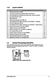
..., USB1314) 13. ATX power connectors (24-pin EATXPWR, 4-pin ATX12V) 3. System panel connector (10-1 pin F_PANEL) 11. B85M-G R2.0 B85M-G R2.0 CPU socket LGA1150 ASUS B85M-G R2.0 1-3 Intel® B85 Serial ATA 3.0Gb/s connectors (7-pin SATA3G_1~2 [dark brown]) 10. Front panel audio connector (10-1 pin... AAFP) 17. TPM connector (20-1 pin TPM) 2. DDR3 DIMM slots 6. Clear RTC RAM (2-pin CLRTC) 9. 1.2.4 Layout contents ...
..., USB1314) 13. ATX power connectors (24-pin EATXPWR, 4-pin ATX12V) 3. System panel connector (10-1 pin F_PANEL) 11. B85M-G R2.0 B85M-G R2.0 CPU socket LGA1150 ASUS B85M-G R2.0 1-3 Intel® B85 Serial ATA 3.0Gb/s connectors (7-pin SATA3G_1~2 [dark brown]) 10. Front panel audio connector (10-1 pin... AAFP) 17. TPM connector (20-1 pin TPM) 2. DDR3 DIMM slots 6. Clear RTC RAM (2-pin CLRTC) 9. 1.2.4 Layout contents ...
User Guide
Page 19
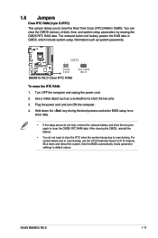
... 12 Normal (Open) Clear CMOS (Short) B85M-G R2.0 Clear RTC RAM To erase the RTC RAM: 1. Hold down and reboot the system, then the BIOS automatically resets parameter settings to default values. Turn OFF the computer and unplug the power cord. 2.... and system setup parameters by erasing the CMOS RTC RAM data. Plug the power cord and turn ON the computer. 4. The onboard button cell battery powers the RAM data in CMOS. Shut down the key during the boot process and enter BIOS setup to overclocking, use the CPU Parameter Recall (C.P.R.) feature. ASUS B85M-G R2.0 1-11
... 12 Normal (Open) Clear CMOS (Short) B85M-G R2.0 Clear RTC RAM To erase the RTC RAM: 1. Hold down and reboot the system, then the BIOS automatically resets parameter settings to default values. Turn OFF the computer and unplug the power cord. 2.... and system setup parameters by erasing the CMOS RTC RAM data. Plug the power cord and turn ON the computer. 4. The onboard button cell battery powers the RAM data in CMOS. Shut down the key during the boot process and enter BIOS setup to overclocking, use the CPU Parameter Recall (C.P.R.) feature. ASUS B85M-G R2.0 1-11

User Guide
Page 36
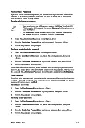
... • If the system fails to boot after changing any BIOS setting, try to clear the CMOS and reset the motherboard to erase the RTC RAM. BIOS menu screen The BIOS setup program can change modes from the Exit menu or from the operating system. • The BIOS setup screens shown... performance mode and boot device priority. The BIOS screens include navigation keys and brief online help to guide you to your screen. • Visit the ASUS website at startup: • Press during the Power-On Self Test (POST). Select the Load Optimized Defaults item under two modes: EZ Mode and ...
... • If the system fails to boot after changing any BIOS setting, try to clear the CMOS and reset the motherboard to erase the RTC RAM. BIOS menu screen The BIOS setup program can change modes from the Exit menu or from the operating system. • The BIOS setup screens shown... performance mode and boot device priority. The BIOS screens include navigation keys and brief online help to guide you to your screen. • Visit the ASUS website at startup: • Press during the Power-On Self Test (POST). Select the Load Optimized Defaults item under two modes: EZ Mode and ...
User Guide
Page 41
... password, erase the CMOS Real Time Clock (RTC) RAM to erase the RTC RAM. • The Administrator or User Password items on top of the screen shows the default Not Installed. From the Enter Current Password box, key in the current password, then press . 3. ASUS B85M-G R2.0 2-11 Administrator Password If you have set an...
... password, erase the CMOS Real Time Clock (RTC) RAM to erase the RTC RAM. • The Administrator or User Password items on top of the screen shows the default Not Installed. From the Enter Current Password box, key in the current password, then press . 3. ASUS B85M-G R2.0 2-11 Administrator Password If you have set an...


