
User Manual
Page 6
... where: • Access can only be gained by SERVICE PERSONS or by USERS who have been instructed about the reasons for the restrictions applied to the location and about any precautions that the power cables for the devices are unplugged before the signal cables are connected. Safety information Electrical Safety • Before installing or removing signal cables, ensure that the power cables for the system...
... where: • Access can only be gained by SERVICE PERSONS or by USERS who have been instructed about the reasons for the restrictions applied to the location and about any precautions that the power cables for the devices are unplugged before the signal cables are connected. Safety information Electrical Safety • Before installing or removing signal cables, ensure that the power cables for the system...

User Manual
Page 8
... This chapter describes how to change system settings through the BIOS Setup menus and describes the BIOS parameters. 5. Chapter 5: Driver Installation This chapter provides instructions for installing the necessary drivers for system integrators, and experienced users with at least basic knowledge of the server, including sections on front panel and rear panel specifications. 2. Contents This guide contains the following parts: 1. Chapter 2: Hardware Setup This chapter lists the hardware setup procedures that you have...
... This chapter describes how to change system settings through the BIOS Setup menus and describes the BIOS parameters. 5. Chapter 5: Driver Installation This chapter provides instructions for installing the necessary drivers for system integrators, and experienced users with at least basic knowledge of the server, including sections on front panel and rear panel specifications. 2. Contents This guide contains the following parts: 1. Chapter 2: Hardware Setup This chapter lists the hardware setup procedures that you have...
User Manual
Page 13
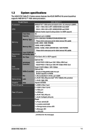
... VGA Aspeed AST2600 Front I/O ports 1 x USB 3.2 Gen 1 port 2 x USB 3.2 Gen 1 ports 1 x VGA port Rear I/O ports 1 x COM port 2 x RJ45 10G LAN ports 1 x RJ45 1G Mgmt LAN ports Front: Switch/LED 1 x Power switch/LED 1 x Location switch/LED 1 x Storage device access LED 1 x Message LED 2 x LAN LED (continued on the next page) ASUS ESC N4A-E11 1-3 SKU 1: HGX A100 4-GPU 40GB(160GB total) 400W - ASUS PIKE II 3008 8-port SAS 12Gb/s HBA Card - 1.3 System specifications The ASUS ESC N4A-E11 Series servers features the ASUS KMPN-U16 server board that supports AMD EPYC™ 7003...
... VGA Aspeed AST2600 Front I/O ports 1 x USB 3.2 Gen 1 port 2 x USB 3.2 Gen 1 ports 1 x VGA port Rear I/O ports 1 x COM port 2 x RJ45 10G LAN ports 1 x RJ45 1G Mgmt LAN ports Front: Switch/LED 1 x Power switch/LED 1 x Location switch/LED 1 x Storage device access LED 1 x Message LED 2 x LAN LED (continued on the next page) ASUS ESC N4A-E11 1-3 SKU 1: HGX A100 4-GPU 40GB(160GB total) 400W - ASUS PIKE II 3008 8-port SAS 12Gb/s HBA Card - 1.3 System specifications The ASUS ESC N4A-E11 Series servers features the ASUS KMPN-U16 server board that supports AMD EPYC™ 7003...

User Manual
Page 14
... specifications Model Name Switch/LED OS Support Out of Band Management Remote Solution Hardware Software Dimension Net Weight Kg (CPU, DRAM & HDD not included) Gross Weight Kg (CPU, DRAM & HDD not included, Packing include) Power Supply (following different configuration by region) Environment Rear: ESC N4A-E11 1 x Power switch/LED 1 x Location switch LED 1 x Q-code/Port 80 LED Windows® Server 2019 RedHat® SuSE® Ubuntu Vmware * Please find the latest OS support from https://www.asus.com/event/ Server/OS_support_list/OS.html ASMB10-iKVM (on-board) ASUS Control...
... specifications Model Name Switch/LED OS Support Out of Band Management Remote Solution Hardware Software Dimension Net Weight Kg (CPU, DRAM & HDD not included) Gross Weight Kg (CPU, DRAM & HDD not included, Packing include) Power Supply (following different configuration by region) Environment Rear: ESC N4A-E11 1 x Power switch/LED 1 x Location switch LED 1 x Q-code/Port 80 LED Windows® Server 2019 RedHat® SuSE® Ubuntu Vmware * Please find the latest OS support from https://www.asus.com/event/ Server/OS_support_list/OS.html ASMB10-iKVM (on-board) ASUS Control...

User Manual
Page 17
PCIe riser card (1 x Gen4 x16 link, supports OCP 3.0 card using a OCP 3.0 slot baseboard) 8. WARNING HAZARDOUS MOVING PARTS KEEP FINGERS AND OTHER BODY PARTS AWAY ASUS ESC N4A-E11 1-7 Rear GPU fans 5. PCIe riser card (2 x Gen4 x16 link) 9. GPU with air cooling modules A protection film is pre-attached to the front cover before turning on the system for proper heat dissipation. SATA/SAS/NVMe backplane 6. 4 x 3.5" storage device bays 7. Front GPU fans 2. ASUS KMPN-U16 server board 3. System fans 4. 1.6 Internal features The server system includes the basic components...
PCIe riser card (1 x Gen4 x16 link, supports OCP 3.0 card using a OCP 3.0 slot baseboard) 8. WARNING HAZARDOUS MOVING PARTS KEEP FINGERS AND OTHER BODY PARTS AWAY ASUS ESC N4A-E11 1-7 Rear GPU fans 5. PCIe riser card (2 x Gen4 x16 link) 9. GPU with air cooling modules A protection film is pre-attached to the front cover before turning on the system for proper heat dissipation. SATA/SAS/NVMe backplane 6. 4 x 3.5" storage device bays 7. Front GPU fans 2. ASUS KMPN-U16 server board 3. System fans 4. 1.6 Internal features The server system includes the basic components...
User Manual
Page 19
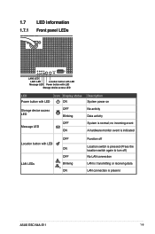
...LAN2 LED LAN1 LED Location button with LED Message LED Power button with LED Storage device access LED LED Icon Display status Power button with LED LAN LEDs OFF ON OFF Blinking ON Function off Location switch is pressed (Press the location switch again to turn off) No LAN connection LAN is transmitting or receiving data LAN connection is normal; no incoming event A hardware monitor event is indicated Location button with LED ON Storage device access LED OFF Blinking OFF Message LED ON Description System power on No activity Data activity System is present ASUS ESC N4A-E11...
...LAN2 LED LAN1 LED Location button with LED Message LED Power button with LED Storage device access LED LED Icon Display status Power button with LED LAN LEDs OFF ON OFF Blinking ON Function off Location switch is pressed (Press the location switch again to turn off) No LAN connection LAN is transmitting or receiving data LAN connection is normal; no incoming event A hardware monitor event is indicated Location button with LED ON Storage device access LED OFF Blinking OFF Message LED ON Description System power on No activity Data activity System is present ASUS ESC N4A-E11...
User Manual
Page 20
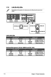
...ASMB10 and DM_LAN1) ACT/LINK LED Status Description OFF No link ORANGE Linked BLINKING Data activity SPEED LED Status Description OFF 10 Mbps connection ORANGE 100 Mbps connection GREEN 1 Gbps connection 1-10 Chapter 1: Product Introduction ACT/LINK LED SPEED LED ACT/LINK LED SPEED LED LAN1/LAN2 LEDs ACT/LINK LED Status Description OFF No link GREEN Linked BLINKING Data activity SPEED LED ACT/LINK LED SPEED LED Status Description OFF 10 Mbps connection ORANGE 100 Mbps connection GREEN 1 Gbps connection Dedicated Management LAN (for all models.
...ASMB10 and DM_LAN1) ACT/LINK LED Status Description OFF No link ORANGE Linked BLINKING Data activity SPEED LED Status Description OFF 10 Mbps connection ORANGE 100 Mbps connection GREEN 1 Gbps connection 1-10 Chapter 1: Product Introduction ACT/LINK LED SPEED LED ACT/LINK LED SPEED LED LAN1/LAN2 LEDs ACT/LINK LED Status Description OFF No link GREEN Linked BLINKING Data activity SPEED LED ACT/LINK LED SPEED LED Status Description OFF 10 Mbps connection ORANGE 100 Mbps connection GREEN 1 Gbps connection Dedicated Management LAN (for all models.
User Manual
Page 21
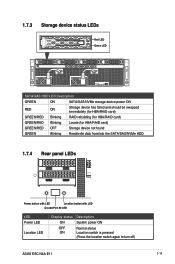
... ON Stroage device has failed and should be swapped immediately (for HBA/RAID card) GREEN/RED Blinking RAID rebuilding (for HBA/RAID card) GREEN/RED Blinking Locate (for HBA/RAID card) GREEN/RED OFF Storage device not found GREEN Blinking Read/write data from/into the SATA/SAS/NVMe HDD 1.7.4 Rear panel LEDs Power button with LED Location button with LED Q-code/Port 80 LED LED Power LED Location LED Display status ON OFF ON Description System power ON Normal status Location switch is pressed (Press the location switch again to turn off) ASUS ESC N4A-E11 1-11
... ON Stroage device has failed and should be swapped immediately (for HBA/RAID card) GREEN/RED Blinking RAID rebuilding (for HBA/RAID card) GREEN/RED Blinking Locate (for HBA/RAID card) GREEN/RED OFF Storage device not found GREEN Blinking Read/write data from/into the SATA/SAS/NVMe HDD 1.7.4 Rear panel LEDs Power button with LED Location button with LED Q-code/Port 80 LED LED Power LED Location LED Display status ON OFF ON Description System power ON Normal status Location switch is pressed (Press the location switch again to turn off) ASUS ESC N4A-E11 1-11
User Manual
Page 23
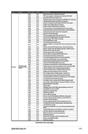
... matching the BIOS public key token The BIOS OEM public key of : Illegal command, Unclaimed cycle, or Host time out An smbus transaction collision detected, operation restarted Transaction failed to be 0x400_0000) No physical x86 cores were found Generic error indicating the CCP HAL initialization failed failure to copy NVRAM to SMU not available. SMU reported an error Function RunPostX86ReleaseUnitTests failed in memcmp() Interface between...
... matching the BIOS public key token The BIOS OEM public key of : Illegal command, Unclaimed cycle, or Host time out An smbus transaction collision detected, operation restarted Transaction failed to be 0x400_0000) No physical x86 cores were found Generic error indicating the CCP HAL initialization failed failure to copy NVRAM to SMU not available. SMU reported an error Function RunPostX86ReleaseUnitTests failed in memcmp() Interface between...

User Manual
Page 51
Intermediate rail connector Pivot receptor Inner rail connector (hidden) Inner receptor Intermediate rail connector Outer receptor The installation steps in this section uses a Left pivot configuration as an example, the installation steps for a Right pivot configuration is similar. 4. Align and connect the outer receptor on the CMA with the connector on the rack rails. Align the three receptors on the CMA with the connector on the inner rail. 5. 3. Align and connect the inner receptor on the CMA with the connectors on the intermediate rail. ASUS ESC N4A-E11 3-9
Intermediate rail connector Pivot receptor Inner rail connector (hidden) Inner receptor Intermediate rail connector Outer receptor The installation steps in this section uses a Left pivot configuration as an example, the installation steps for a Right pivot configuration is similar. 4. Align and connect the outer receptor on the CMA with the connector on the rack rails. Align the three receptors on the CMA with the connector on the inner rail. 5. 3. Align and connect the inner receptor on the CMA with the connectors on the intermediate rail. ASUS ESC N4A-E11 3-9

User Manual
Page 62
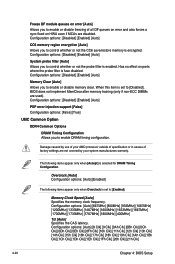
... processor operating at your hard drives when enabling this item to boost the CPU's frequency. Engine Boost [Disabled] Enable this feature. Configuration options: [Disabled] [Enabled] Operate with an ambient temperature of the system and the CPU. Please use an external PCIe storage controller for your own risk. 4-10 Chapter 4: BIOS Setup Configuration options: [Disabled] [Enabled] Please note that overclocking might cause component damage or system crashes, which may vary by version of workloads. For Windows Server...
... processor operating at your hard drives when enabling this item to boost the CPU's frequency. Engine Boost [Disabled] Enable this feature. Configuration options: [Disabled] [Enabled] Operate with an ambient temperature of the system and the CPU. Please use an external PCIe storage controller for your own risk. 4-10 Chapter 4: BIOS Setup Configuration options: [Disabled] [Enabled] Please note that overclocking might cause component damage or system crashes, which may vary by version of workloads. For Windows Server...
User Manual
Page 72
... when Overclock is set to [Enabled]. Configuration options: [Disabled] [Enabled] [Auto] CC6 memory region encryption [Auto] Allows you to control whether or not the CC6 save/restore memory is selected for DRAM Timing Configuration. Damage caused by use of your AMD processor outside of specification or in excess of all DF queues on error and also forces a sync flood on parts where the probe...
... when Overclock is set to [Enabled]. Configuration options: [Disabled] [Enabled] [Auto] CC6 memory region encryption [Auto] Allows you to control whether or not the CC6 save/restore memory is selected for DRAM Timing Configuration. Damage caused by use of your AMD processor outside of specification or in excess of all DF queues on error and also forces a sync flood on parts where the probe...
User Manual
Page 78
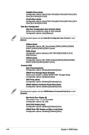
.../1] [RZQ/5] [RZQ/3] [RZQ/7] [Auto] Common RAS Data Poisoning [Auto] Configuration options: [Enabled] [Disabled] [Auto] DRAM Post Package Repair [Disable] Allows you to specify the mode for drive strength. Configuration options: [0] - [39] Write CRC Enable [Auto] Configuration options: [Enabled] [Disabled] [Auto] DRAM Write CRC Enable and Retry Limit [Auto] Configuration options: [Enabled] [Disabled] [Auto] 4-26 Chapter 4: BIOS Setup Configuration options: [Auto] [Manual] The following item appears only when DRAM Address Command Parity Retry is set to [Enabled].
.../1] [RZQ/5] [RZQ/3] [RZQ/7] [Auto] Common RAS Data Poisoning [Auto] Configuration options: [Enabled] [Disabled] [Auto] DRAM Post Package Repair [Disable] Allows you to specify the mode for drive strength. Configuration options: [0] - [39] Write CRC Enable [Auto] Configuration options: [Enabled] [Disabled] [Auto] DRAM Write CRC Enable and Retry Limit [Auto] Configuration options: [Enabled] [Disabled] [Auto] 4-26 Chapter 4: BIOS Setup Configuration options: [Auto] [Manual] The following item appears only when DRAM Address Command Parity Retry is set to [Enabled].
User Manual
Page 82
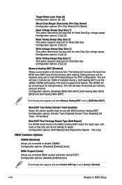
... attempt to repair. Configuration options: [Vendor Tests Enabled] [Vendor Tests Disabled] [All Tests - The testing will be repaired using soft or hard PPR depending on the PPC configuration. The test will take 10 seconds per memory rank per 16GN of installed memory. All Vendors] Mem BIST Post Package Repair Type [Soft Repair] For DRAM errors found in the BIOS memory BIST select the repair type, soft, hard, or test only and do a hard repair for write Data Eye. Configuration options: [1] [2] [4] Write...
... attempt to repair. Configuration options: [Vendor Tests Enabled] [Vendor Tests Disabled] [All Tests - The testing will be repaired using soft or hard PPR depending on the PPC configuration. The test will take 10 seconds per memory rank per 16GN of installed memory. All Vendors] Mem BIST Post Package Repair Type [Soft Repair] For DRAM errors found in the BIOS memory BIST select the repair type, soft, hard, or test only and do a hard repair for write Data Eye. Configuration options: [1] [2] [4] Write...
User Manual
Page 83
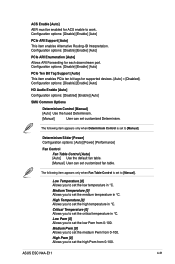
... [Power] Configuration options: [Auto] [Power] [Performance] Fan Control Fan Table Control [Auto] [Auto] Use the default fan table. [Manual] User can set the critical temperature in °C. Critical Temperature [0] Allows you to set customized Determinism. High Pwm [0] Allows you to set to work. Configuration options: [Disable] [Enable] [Auto] PCIe Ten Bit Tag Support [Auto] This item enables PCIe ten bit tags for each downstream port. Low Pwm [0] Allows you to set the medium Pwm from 0-100. Configuration options: [Disable] [Enable] [Auto] PCIe...
... [Power] Configuration options: [Auto] [Power] [Performance] Fan Control Fan Table Control [Auto] [Auto] Use the default fan table. [Manual] User can set the critical temperature in °C. Critical Temperature [0] Allows you to set customized Determinism. High Pwm [0] Allows you to set to work. Configuration options: [Disable] [Enable] [Auto] PCIe Ten Bit Tag Support [Auto] This item enables PCIe ten bit tags for each downstream port. Low Pwm [0] Allows you to set the medium Pwm from 0-100. Configuration options: [Disable] [Enable] [Auto] PCIe...
User Manual
Page 99
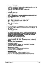
... data. Configuration options: [VT100] [LINUX] [XTERMR6] [SCO] [ESCN] [VT400] ASUS ESC N4A-E11 4-47 Long or noisy lines may require more than 1 stop bit. The speed must be sent with slow devices may require lower speeds. Configuration options: [None] [Hardware RTS/CTS] VT -UTF8 Combo Key Support [Enabled] This allows you enable or disable extended terminal resolution. Bits per second [115200] Selects serial port transmission speed. Configuration options: [1] [2] Flow Control [None] Flow control can be sent. Hardware flow control uses...
... data. Configuration options: [VT100] [LINUX] [XTERMR6] [SCO] [ESCN] [VT400] ASUS ESC N4A-E11 4-47 Long or noisy lines may require more than 1 stop bit. The speed must be sent with slow devices may require lower speeds. Configuration options: [None] [Hardware RTS/CTS] VT -UTF8 Combo Key Support [Enabled] This allows you enable or disable extended terminal resolution. Bits per second [115200] Selects serial port transmission speed. Configuration options: [1] [2] Flow Control [None] Flow control can be sent. Hardware flow control uses...
User Manual
Page 100
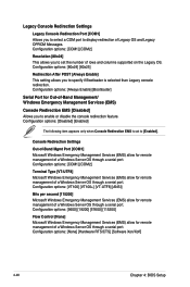
... Messages. Configuration options: [None] [Hardware RTS/CTS] [Software Xon/Xoff] 4-48 Chapter 4: BIOS Setup Configuration options: [COM1] [COM2] Terminal Type [VT-UTF8] Microsoft Windows Emergency Management Services (EMS) allow for remote management of a Windows Server OS through a serial port. Legacy Console Redirection Settings Legacy Console Redirection Port [COM1] Allows you to enable or disable the console redirection feature. Configuration options: [VT100] [VT100+] [VT-UTF8] [ANSI] Bits per second [115200] Microsoft Windows Emergency Management Services (EMS) allow for remote...
... Messages. Configuration options: [None] [Hardware RTS/CTS] [Software Xon/Xoff] 4-48 Chapter 4: BIOS Setup Configuration options: [COM1] [COM2] Terminal Type [VT-UTF8] Microsoft Windows Emergency Management Services (EMS) allow for remote management of a Windows Server OS through a serial port. Legacy Console Redirection Settings Legacy Console Redirection Port [COM1] Allows you to enable or disable the console redirection feature. Configuration options: [VT100] [VT100+] [VT-UTF8] [ANSI] Bits per second [115200] Microsoft Windows Emergency Management Services (EMS) allow for remote...
User Manual
Page 102
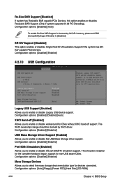
...IO Virtualization Support if the system has SRIOV capable PCIe devices. The XHCI ownership change should be claimed by XHCI driver. Configuration options: [Auto] [Floppy] [Forced FDD] [Hard Disk] [CD-ROM] 4-50 Chapter 4: BIOS Setup Configuration options: [Disabled] [Enabled] Mass Storage Devices Allows you to enable or disable Legacy USB device support. Configuration options: [Disabled] [Auto] To enable Re-Size BAR Support for harnessing full GPU memory, please set CSM (Compatibility Support Module) to enable or disable the USB Mass Storage driver support. Configuration options...
...IO Virtualization Support if the system has SRIOV capable PCIe devices. The XHCI ownership change should be claimed by XHCI driver. Configuration options: [Auto] [Floppy] [Forced FDD] [Hard Disk] [CD-ROM] 4-50 Chapter 4: BIOS Setup Configuration options: [Disabled] [Enabled] Mass Storage Devices Allows you to enable or disable Legacy USB device support. Configuration options: [Disabled] [Auto] To enable Re-Size BAR Support for harnessing full GPU memory, please set CSM (Compatibility Support Module) to enable or disable the USB Mass Storage driver support. Configuration options...
User Manual
Page 111
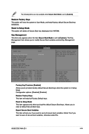
... clear all default Secure Boot keys. ASUS ESC N4A-E11 4-59 Restore Factory Keys This option will ask you if you to User Mode, and install factory default Secure Boot key databases. Factory Key Provision [Enabled] Allows you want to provision factory default Secure Boot keys when the system is in Setup Mode. Configuration options: [Disabled] [Enabled] Restore Factory Keys This item will delete all secure boot variables. Select Yes if you to save all Factory Default keys. The Key Management...
... clear all default Secure Boot keys. ASUS ESC N4A-E11 4-59 Restore Factory Keys This option will ask you if you to User Mode, and install factory default Secure Boot key databases. Factory Key Provision [Enabled] Allows you want to provision factory default Secure Boot keys when the system is in Setup Mode. Configuration options: [Disabled] [Enabled] Restore Factory Keys This item will delete all secure boot variables. Select Yes if you to save all Factory Default keys. The Key Management...
User Manual
Page 112
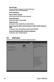
...] [Delete] Authorized TimeStamps (DBT) / OsRecovery Signatures Configuration options: [Update] [Append] 4.8 Boot menu The Boot menu items allow the image to run in Secure Boot mode. Configuration options: [Set New] [Append] Device Guard Ready Remove 'UEFI CA' from DB Remove Microsoft UEFI CA from Secure Boot DB. Restore DB defaults Restore DB variable to factory defaults. Enroll Efi Image This item will allow you to change the system boot options. 4-60 Chapter 4: BIOS Setup
...] [Delete] Authorized TimeStamps (DBT) / OsRecovery Signatures Configuration options: [Update] [Append] 4.8 Boot menu The Boot menu items allow the image to run in Secure Boot mode. Configuration options: [Set New] [Append] Device Guard Ready Remove 'UEFI CA' from DB Remove Microsoft UEFI CA from Secure Boot DB. Restore DB defaults Restore DB variable to factory defaults. Enroll Efi Image This item will allow you to change the system boot options. 4-60 Chapter 4: BIOS Setup


