Users Manual English
Page 3
Contents Safety information iv About this guide iv Package contents vi EX-A320M-GAMING specifications summary vi Chapter 1 Product introduction Motherboard overview 1-1 Central Processing Unit (CPU 1-7 System memory 1-9 Chapter 2 BIOS information BIOS setup program 2-1 I-Cafe ...2-2 Main menu 2-3 Ai Tweaker 2-4 Advanced menu 2-6 Monitor menu 2-8 Boot menu 2-9 Tool menu 2-11 Exit menu 2-12 Appendix Notices...A-1 ASUS contact information A-4 iii
Contents Safety information iv About this guide iv Package contents vi EX-A320M-GAMING specifications summary vi Chapter 1 Product introduction Motherboard overview 1-1 Central Processing Unit (CPU 1-7 System memory 1-9 Chapter 2 BIOS information BIOS setup program 2-1 I-Cafe ...2-2 Main menu 2-3 Ai Tweaker 2-4 Advanced menu 2-6 Monitor menu 2-8 Boot menu 2-9 Tool menu 2-11 Exit menu 2-12 Appendix Notices...A-1 ASUS contact information A-4 iii
Users Manual English
Page 4
... supports. About this guide is broken, do not try to moisture. • Place the product on the motherboard. • Chapter 2: BIOS information This chapter discusses changing system settings through the BIOS Setup menus. These devices could interrupt the grounding circuit. • Ensure that the power cables for the devices are unplugged before...
... supports. About this guide is broken, do not try to moisture. • Place the product on the motherboard. • Chapter 2: BIOS information This chapter discusses changing system settings through the BIOS Setup menus. These devices could interrupt the grounding circuit. • Ensure that the power cables for the devices are unplugged before...

Users Manual English
Page 7
...ASUS SafeSlot ASUS 5X PROTECTION III - ASUS EZ Flash 3 Optimized cooling - Aura RGB Strip Headers Superb performance UEFI BIOS - Enhanced DRAM overcurrent protection - ASUS Q-Slot UEFI BIOS EZ Mode - ASUS Fan Xpert (continued on the next page) vii ASUS Overvoltage Protection - ASUS Q-DIMM - EX-A320M-GAMING specifications summary LAN Storage USB ASUS... time Easy PC DIY Q-Design - ASUS Stainless Steel Back I/O - 3X more durable Aura - ASUS CrashFree BIOS 3 - Stylish Fanless Design: Chipset Heat-sink solution - ASUS SafeSlot Core - featuring friendly graphics user...
...ASUS SafeSlot ASUS 5X PROTECTION III - ASUS EZ Flash 3 Optimized cooling - Aura RGB Strip Headers Superb performance UEFI BIOS - Enhanced DRAM overcurrent protection - ASUS Q-Slot UEFI BIOS EZ Mode - ASUS Fan Xpert (continued on the next page) vii ASUS Overvoltage Protection - ASUS Q-DIMM - EX-A320M-GAMING specifications summary LAN Storage USB ASUS... time Easy PC DIY Q-Design - ASUS Stainless Steel Back I/O - 3X more durable Aura - ASUS CrashFree BIOS 3 - Stylish Fanless Design: Chipset Heat-sink solution - ASUS SafeSlot Core - featuring friendly graphics user...

Users Manual English
Page 8
EX-A320M-GAMING specifications summary Rear panel I/O ports Internal connectors BIOS features Manageability Support DVD OS support Form factor 1 x PS/2 keyboard (purple) 1 x PS/2 mouse port (green) 1 x HDMI port 1 x DVI-D port 1 x LAN (RJ-45) port...RTC RAM (2 pin) 1 x System panel connector 1 x RGB header 128 Mb Flash ROM, UEFI AMI BIOS, PnP, DMI3.0, WfM2.0, SM BIOS 3.0, ACPI 6.1, Multi-language BIOS, ASUS EZ Flash 3, ASUS CrashFree BIOS 3, I-CAFE, Last Modified log, F12 PrintScreen, ASUS DRAM SPD (Serial Presence Detect) memory information, F6 Qfan Control WfM 2.0, DMI 3.0, WOL by PME, PXE...
EX-A320M-GAMING specifications summary Rear panel I/O ports Internal connectors BIOS features Manageability Support DVD OS support Form factor 1 x PS/2 keyboard (purple) 1 x PS/2 mouse port (green) 1 x HDMI port 1 x DVI-D port 1 x LAN (RJ-45) port...RTC RAM (2 pin) 1 x System panel connector 1 x RGB header 128 Mb Flash ROM, UEFI AMI BIOS, PnP, DMI3.0, WfM2.0, SM BIOS 3.0, ACPI 6.1, Multi-language BIOS, ASUS EZ Flash 3, ASUS CrashFree BIOS 3, I-CAFE, Last Modified log, F12 PrintScreen, ASUS DRAM SPD (Serial Presence Detect) memory information, F6 Qfan Control WfM 2.0, DMI 3.0, WOL by PME, PXE...

Users Manual English
Page 9
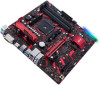
... AM4 Place this side towards the rear of the chassis HDMI U31G1_56 12 U31G1_34 CHA_FAN BATTERY 24.4cm(9.6in) SATA6G_4 LAN_USB12 128Mb BIOS AIO_PUMP 15 AUDIO Realtek® 8111H 17 EX-A320M-GAMING PCIEX16 M.2(SOCKET3) 16 Super I/O PCIEX1 22110 2280 2260 2242 AMD A320 AURA M.2(SOCKET3) PCIE SATA X4 V ALC PCIEX4 6 887 15 COM... you install or remove any component, ensure that the ATX power supply is switched off or the power cord is detached from the power supply. ASUS EX-A320M-GAMING 1-1
... AM4 Place this side towards the rear of the chassis HDMI U31G1_56 12 U31G1_34 CHA_FAN BATTERY 24.4cm(9.6in) SATA6G_4 LAN_USB12 128Mb BIOS AIO_PUMP 15 AUDIO Realtek® 8111H 17 EX-A320M-GAMING PCIEX16 M.2(SOCKET3) 16 Super I/O PCIEX1 22110 2280 2260 2242 AMD A320 AURA M.2(SOCKET3) PCIE SATA X4 V ALC PCIEX4 6 887 15 COM... you install or remove any component, ensure that the ATX power supply is switched off or the power cord is detached from the power supply. ASUS EX-A320M-GAMING 1-1

Users Manual English
Page 11
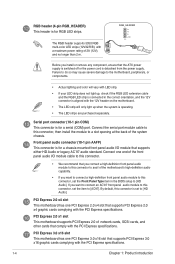
...connector is for additional USB 3.0 front or rear panel ports. PIN 1 2. Hold down the key during the boot process and enter BIOS setup to clear the CMOS RTC RAM data. This connector complies with USB 3.0 specifications and provide faster data transfer speeds of the system... up to 480Mbps connection speed. TPM +3VSB S_PCIRST#_TBD GND C_PCICLK_TPM +3V +3V F_CLKRUN F_SERIRQ F_FRAME# F_LAD3 F_LAD2 F_LAD1 F_LAD0 PIN 1 ASUS EX-A320M-GAMING 1-3 System panel connector (10-1 pin F_PANEL) This connector supports several chassis-mounted functions. If the steps above do not help, remove ...
...connector is for additional USB 3.0 front or rear panel ports. PIN 1 2. Hold down the key during the boot process and enter BIOS setup to clear the CMOS RTC RAM data. This connector complies with USB 3.0 specifications and provide faster data transfer speeds of the system... up to 480Mbps connection speed. TPM +3VSB S_PCIRST#_TBD GND C_PCICLK_TPM +3V +3V F_CLKRUN F_SERIRQ F_FRAME# F_LAD3 F_LAD2 F_LAD1 F_LAD0 PIN 1 ASUS EX-A320M-GAMING 1-3 System panel connector (10-1 pin F_PANEL) This connector supports several chassis-mounted functions. If the steps above do not help, remove ...
Users Manual English
Page 12
... a serial (COM) port. Connect the serial port module cable to [HD Audio]. Front panel audio connector (10-1 pin AAFP) This connector is connected in the BIOS setup to [AC97]. If you want to connect an AC'97 front panel audio module to this connector, set the item to [HD Audio].
... a serial (COM) port. Connect the serial port module cable to [HD Audio]. Front panel audio connector (10-1 pin AAFP) This connector is connected in the BIOS setup to [AC97]. If you want to connect an AC'97 front panel audio module to this connector, set the item to [HD Audio].

Users Manual English
Page 19
... button, reset button, or the ++ keys to force reset from the operating system. • The BIOS setup screens shown in using the first two options. Select the Load Optimized Defaults item under the Advanced Mode. 2-1 ASUS EX-A320M-GAMING If you do not press or , POST continues with its parameters. See section Motherboard overview for...
... button, reset button, or the ++ keys to force reset from the operating system. • The BIOS setup screens shown in using the first two options. Select the Load Optimized Defaults item under the Advanced Mode. 2-1 ASUS EX-A320M-GAMING If you do not press or , POST continues with its parameters. See section Motherboard overview for...

Users Manual English
Page 20
... Flash 3. Press [Enter] to 10 seconds. The values range from 0 to launch the ASUS EZ Flash 3 screen. You can only execute the POST delay time during Normal Boot. Realtek PXE Option ROM This item allows you to enable or ... for the I -Cafe The items in this menu allows you to select the desired additional POST waiting time to be pressed when error occurs. Chapter 2: BIOS information 2-2 POST Delay Time [3 sec] This item allows you to configure some quick settings for the F1 key to easily enter the...
... Flash 3. Press [Enter] to 10 seconds. The values range from 0 to launch the ASUS EZ Flash 3 screen. You can only execute the POST delay time during Normal Boot. Realtek PXE Option ROM This item allows you to enable or ... for the I -Cafe The items in this menu allows you to select the desired additional POST waiting time to be pressed when error occurs. Chapter 2: BIOS information 2-2 POST Delay Time [3 sec] This item allows you to configure some quick settings for the F1 key to easily enter the...

Users Manual English
Page 21
.... 2-3 ASUS EX-A320M-GAMING After you to set the system time. System Time [xx:xx:xx] Allows you set the system date, time, language, and security settings. System Language [English] Allows you to set the system date. Configuration options: [English] System Date [Day xx/xx/xxxx] Allows you to clear the BIOS password.... the system security settings. • If you to erase the RTC RAM. • The Administrator or User Password items on top of the BIOS Setup program. The Main menu provides you an overview of the basic system information, and allows you have forgotten your...
.... 2-3 ASUS EX-A320M-GAMING After you to set the system time. System Time [xx:xx:xx] Allows you set the system date, time, language, and security settings. System Language [English] Allows you to set the system date. Configuration options: [English] System Date [Day xx/xx/xxxx] Allows you to clear the BIOS password.... the system security settings. • If you to erase the RTC RAM. • The Administrator or User Password items on top of the BIOS Setup program. The Main menu provides you an overview of the basic system information, and allows you have forgotten your...

Users Manual English
Page 22
... when changing the settings of the Extreme Tweaker menu items. Incorrect field values can also key in the desired value using the numeric keypad. Chapter 2: BIOS information 2-4 The configurable options vary with the BCLK (base clock) frequency setting.
... when changing the settings of the Extreme Tweaker menu items. Incorrect field values can also key in the desired value using the numeric keypad. Chapter 2: BIOS information 2-4 The configurable options vary with the BCLK (base clock) frequency setting.

Users Manual English
Page 24
...configure the management engine technology settings. You can cause the system to disable the AMD CPU fTPM. SATA Configuration While entering Setup, the BIOS automatically detects the presence of the Advanced menu items. Incorrect field values can select the Firmware TPM to enable the AMD CPU fTPM or... in this menu allow you to adjust the PCH PCI Express speed. The SATA Port items show the CPU-related information that the BIOS automatically detects. Be cautious when changing the settings of SATA devices. APM Configuration The items in this menu allows you to the corresponding...
...configure the management engine technology settings. You can cause the system to disable the AMD CPU fTPM. SATA Configuration While entering Setup, the BIOS automatically detects the presence of the Advanced menu items. Incorrect field values can select the Firmware TPM to enable the AMD CPU fTPM or... in this menu allow you to adjust the PCH PCI Express speed. The SATA Port items show the CPU-related information that the BIOS automatically detects. Be cautious when changing the settings of SATA devices. APM Configuration The items in this menu allows you to the corresponding...
Users Manual English
Page 26
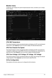
... Voltage The onboard hardware monitor automatically detects the voltage output through the onboard voltage regulators. Select [Ignore] if you to change the fan settings. Chapter 2: BIOS information 2-8 Monitor menu The Monitor menu displays the system temperature/power status, and allows you do not want to detect this menu allows you to...
... Voltage The onboard hardware monitor automatically detects the voltage output through the onboard voltage regulators. Select [Ignore] if you to change the fan settings. Chapter 2: BIOS information 2-8 Monitor menu The Monitor menu displays the system temperature/power status, and allows you do not want to detect this menu allows you to...

Users Manual English
Page 28
... screen depends on the number of devices installed in the system. • To access Windows® OS in the system. Chapter 2: BIOS information 2-10 Boot Option Priorities These items specify the boot device priority sequence from unauthorized access and malwares during system startup, press when... ASUS Logo appears. The number of device items that appears on the screen depends on the number of devices installed in Safe Mode,...
... screen depends on the number of devices installed in the system. • To access Windows® OS in the system. Chapter 2: BIOS information 2-10 Boot Option Priorities These items specify the boot device priority sequence from unauthorized access and malwares during system startup, press when... ASUS Logo appears. The number of device items that appears on the screen depends on the number of devices installed in Safe Mode,...

Users Manual English
Page 29
...no profile is created. Press [Enter] to display the submenu. Select an item then press to launch the ASUS EZ Flash 3 screen. ASUS SPD Information DIMM Slot number [DIMM_A1] Displays the Serial Presence Detect (SPD) information of the DIMM module ...selected slot. ASUS EZ Flash 3 Utility Allows you to store or load multiple BIOS settings. Configuration options: [Disabled] [Enabled] ASUS Overclocking Profile This item allows you to configure options for special functions. Configuration options: [DIMM_A1] [DIMM_A2] [DIMM_B1] [DIMM_B2] 2-11 ASUS EX-A320M-GAMING Tool menu The...
...no profile is created. Press [Enter] to display the submenu. Select an item then press to launch the ASUS EZ Flash 3 screen. ASUS SPD Information DIMM Slot number [DIMM_A1] Displays the Serial Presence Detect (SPD) information of the DIMM module ...selected slot. ASUS EZ Flash 3 Utility Allows you to store or load multiple BIOS settings. Configuration options: [Disabled] [Enabled] ASUS Overclocking Profile This item allows you to configure options for special functions. Configuration options: [DIMM_A1] [DIMM_A2] [DIMM_B1] [DIMM_B2] 2-11 ASUS EX-A320M-GAMING Tool menu The...

Users Manual English
Page 30
... Changes and Exit This option allows you to exit the Setup program without saving your changes to the BIOS items. Load Optimized Defaults This option allows you to load the default values for the BIOS items, and save changes and exit. Select OK to load the default values. When you select this... Changes & Reset Once you to attempt to launch the EFI Shell application (shellx64.efi) from the Exit menu to save or discard your changes. Chapter 2: BIOS information 2-12
... Changes and Exit This option allows you to exit the Setup program without saving your changes to the BIOS items. Load Optimized Defaults This option allows you to load the default values for the BIOS items, and save changes and exit. Select OK to load the default values. When you select this... Changes & Reset Once you to attempt to launch the EFI Shell application (shellx64.efi) from the Exit menu to save or discard your changes. Chapter 2: BIOS information 2-12


