
User Manual
Page 4
... 2-35 2.8 Onboard LEDs 2-36 2.9 Starting up for the first time 2-38 2.10 Turning off the computer 2-38 Chapter 3: BIOS setup 3.1 Knowing BIOS 3-1 3.2 Updating BIOS 3-1 3.2.1 ASUS Update utility 3-2 3.2.2 ASUS EZ Flash 2 utility 3-4 3.2.3 ASUS CrashFree BIOS 3 utility 3-5 3.2.4 ASUS BIOS Updater 3-6 3.3...3-13 3.4.3 System Information 3-14 3.5 Ai Tweaker menu 3-15 3.5.1 CPU Level UP 3-15 3.5.2 OC Tuner Utility 3-16 3.5.3 Ai Overclock Tuner 3-16 3.5.4 CPU Ratio 3-17 3.5.5 DRAM Frequency 3-17 3.5.6 CPU/NB Frequency 3-17 3.5.7 HT Link Speed 3-17 3.5.8 DRAM Timing...
... 2-35 2.8 Onboard LEDs 2-36 2.9 Starting up for the first time 2-38 2.10 Turning off the computer 2-38 Chapter 3: BIOS setup 3.1 Knowing BIOS 3-1 3.2 Updating BIOS 3-1 3.2.1 ASUS Update utility 3-2 3.2.2 ASUS EZ Flash 2 utility 3-4 3.2.3 ASUS CrashFree BIOS 3 utility 3-5 3.2.4 ASUS BIOS Updater 3-6 3.3...3-13 3.4.3 System Information 3-14 3.5 Ai Tweaker menu 3-15 3.5.1 CPU Level UP 3-15 3.5.2 OC Tuner Utility 3-16 3.5.3 Ai Overclock Tuner 3-16 3.5.4 CPU Ratio 3-17 3.5.5 DRAM Frequency 3-17 3.5.6 CPU/NB Frequency 3-17 3.5.7 HT Link Speed 3-17 3.5.8 DRAM Timing...

User Manual
Page 21
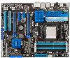
... 2-22 2-21 2-20 2-29 2-27 2-36 2-28 2-34 2-30 2-32 2-29 2-32 Chapter 2 ASUS M4A89TD PRO Series 2-3 DDR3 DIMM slots 5. IEEE 1394a port connector (10-1 pin IE1394_2) 16. CPU, chassis, and power fan connectors (4-pin CPU_FAN, 4-pin CHA_FAN1, 3-pin CHA_FAN2, 3-pin PWR_FAN) 4. Turbo Key... II switch (TURBO_KEY_II) 7. Serial port connector (10-1 pin COM1) 9. Core Unlocker switch (CORE_UNLOCKER) 6. Standby power LED (SB_PWR) 11. ATX ...
... 2-22 2-21 2-20 2-29 2-27 2-36 2-28 2-34 2-30 2-32 2-29 2-32 Chapter 2 ASUS M4A89TD PRO Series 2-3 DDR3 DIMM slots 5. IEEE 1394a port connector (10-1 pin IE1394_2) 16. CPU, chassis, and power fan connectors (4-pin CPU_FAN, 4-pin CHA_FAN1, 3-pin CHA_FAN2, 3-pin PWR_FAN) 4. Turbo Key... II switch (TURBO_KEY_II) 7. Serial port connector (10-1 pin COM1) 9. Core Unlocker switch (CORE_UNLOCKER) 6. Standby power LED (SB_PWR) 11. ATX ...

User Manual
Page 39
... Key II switch lights when the switch setting is powered off. ASUS M4A89TD PRO Series 2-21 Refer to section 2.8 Onboard LEDs for the exact location of the Turbo Key II switch. •...will use the TurboV Auto Tuning, overclock in the BIOS menu follow the current setting of the O2LED5 LED. • If you clear the CMOS or load the BIOS setup defaults, the related overclocking items... after the next system bootup. • You may use the last setting you to auto-tune your CPU to Enable. For ensuring the system performance, turn the switch setting to Enable when the system is turned...
... Key II switch lights when the switch setting is powered off. ASUS M4A89TD PRO Series 2-21 Refer to section 2.8 Onboard LEDs for the exact location of the Turbo Key II switch. •...will use the TurboV Auto Tuning, overclock in the BIOS menu follow the current setting of the O2LED5 LED. • If you clear the CMOS or load the BIOS setup defaults, the related overclocking items... after the next system bootup. • You may use the last setting you to auto-tune your CPU to Enable. For ensuring the system performance, turn the switch setting to Enable when the system is turned...

User Manual
Page 40
Refer to section 2.8 Onboard LEDs for the exact location of the O2LED4 LED. • You may also press during the Power-On-Self-Test (POST) or enable the ASUS Core Unlocker item in the BIOS menu follows the current setting of your CPU. For ensuring the system performance, turn the switch setting to ...Enable when the system is powered off. • The O2LED4 LED near the Core Unlocker switch lights when the ...
Refer to section 2.8 Onboard LEDs for the exact location of the O2LED4 LED. • You may also press during the Power-On-Self-Test (POST) or enable the ASUS Core Unlocker item in the BIOS menu follows the current setting of your CPU. For ensuring the system performance, turn the switch setting to ...Enable when the system is powered off. • The O2LED4 LED near the Core Unlocker switch lights when the ...

User Manual
Page 54
... or plugging in soft‑off mode. The green LED lights up to locate the root problem within a second. POST State LEDs POST State LEDs check key components (CPU, DRAM, VGA card, and HDD) in BIOS. 2.8 Onboard LEDs 1. Refer to the error device will continue lighting until... the problem is solved. Chapter 2 2. You may disable the POST State LEDs in sequence during motherboard booting process...
... or plugging in soft‑off mode. The green LED lights up to locate the root problem within a second. POST State LEDs POST State LEDs check key components (CPU, DRAM, VGA card, and HDD) in BIOS. 2.8 Onboard LEDs 1. Refer to the error device will continue lighting until... the problem is solved. Chapter 2 2. You may disable the POST State LEDs in sequence during motherboard booting process...


