ME-99B User Manual
Page 4
... DMA Channels for ISA Cards 26 3.7.4 ISA Cards and Hardware Monitor 26 3.8 External Connectors 27 3.9 Power Connection Procedures 39 4. FEATURES 8 2.1 The ASUS ME-99B Motherboard 8 2.1.1 Specifications 8 2.1.2 Performance 9 2.1.3 Intelligence 10 2.2 Parts of the ASUS ME-99B Motherboard 11 3. BIOS SETUP 40 4.1 Flash Memory Writer Utility 40 4.1.1 Main Menu 40 4.1.2 Managing and Updating Your BIOS 42 4.2 BIOS Setup Program 43 4.2.1 BIOS Menu Bar 44 4.2.2 Legend Bar 44 4.3 Main Menu 46 4.3.1 Primary & Secondary Master/Slave 47 4 ASUS ME-99B User's Manual INTRODUCTION...
... DMA Channels for ISA Cards 26 3.7.4 ISA Cards and Hardware Monitor 26 3.8 External Connectors 27 3.9 Power Connection Procedures 39 4. FEATURES 8 2.1 The ASUS ME-99B Motherboard 8 2.1.1 Specifications 8 2.1.2 Performance 9 2.1.3 Intelligence 10 2.2 Parts of the ASUS ME-99B Motherboard 11 3. BIOS SETUP 40 4.1 Flash Memory Writer Utility 40 4.1.1 Main Menu 40 4.1.2 Managing and Updating Your BIOS 42 4.2 BIOS Setup Program 43 4.2.1 BIOS Menu Bar 44 4.2.2 Legend Bar 44 4.3 Main Menu 46 4.3.1 Primary & Secondary Master/Slave 47 4 ASUS ME-99B User's Manual INTRODUCTION...
ME-99B User Manual
Page 5
... 4.4.3 PCI Configuration 57 4.4.4 Shadow Configuration 60 4.5 Power Menu 61 4.5.1 Power Up Control 63 4.5.2 Hardware Monitor 64 4.6 Boot Menu 65 4.7 Exit Menu 67 5. SOFTWARE SETUP 69 5.1 Operating Systems 69 5.1.1 Windows 98 First Time Installation 69 5.2 ME-99B Support CD 70 5.2.1 Installation Menu 70 5.3 Install ASUS PC Probe Vx.xx 71 5.4 Install Bus Master IDE Driver 72 5.5 Install VGA Driver 73 5.5.1 Making Monitor Adjustments 74 Video Setting Page 74 Display Modes Page 75 Gamma Correction Page 76 5.6 Install Audio Driver (only with onboard audio option 77 5.7 Install...
... 4.4.3 PCI Configuration 57 4.4.4 Shadow Configuration 60 4.5 Power Menu 61 4.5.1 Power Up Control 63 4.5.2 Hardware Monitor 64 4.6 Boot Menu 65 4.7 Exit Menu 67 5. SOFTWARE SETUP 69 5.1 Operating Systems 69 5.1.1 Windows 98 First Time Installation 69 5.2 ME-99B Support CD 70 5.2.1 Installation Menu 70 5.3 Install ASUS PC Probe Vx.xx 71 5.4 Install Bus Master IDE Driver 72 5.5 Install VGA Driver 73 5.5.1 Making Monitor Adjustments 74 Video Setting Page 74 Display Modes Page 75 Gamma Correction Page 76 5.6 Install Audio Driver (only with onboard audio option 77 5.7 Install...
ME-99B User Manual
Page 7
... floppy disk drives (1) Ribbon cable for VGA with mounting bracket (1) Connector set for serial ports (1) Connector set for PS/2 mouse and parallel port (1) Bag of spare jumper caps (1) Support CD with drivers and utilities (1) This Motherboard User's Manual Connector set for TV Out (with TV Out chip onboard) Connector set for LCD (with LCD chip onboard) Connector set for audio input/output and game/MIDI port (with audio chip onboard) ASUS IrDA-compliant infrared module (optional) ASUS USB/MIR module (optional) ASUS PCI-L101 Wake-On-LAN 10/100 Fast Ethernet Card (optional) ASUS ME-99B User...
... floppy disk drives (1) Ribbon cable for VGA with mounting bracket (1) Connector set for serial ports (1) Connector set for PS/2 mouse and parallel port (1) Bag of spare jumper caps (1) Support CD with drivers and utilities (1) This Motherboard User's Manual Connector set for TV Out (with TV Out chip onboard) Connector set for LCD (with LCD chip onboard) Connector set for audio input/output and game/MIDI port (with audio chip onboard) ASUS IrDA-compliant infrared module (optional) ASUS USB/MIR module (optional) ASUS PCI-L101 Wake-On-LAN 10/100 Fast Ethernet Card (optional) ASUS ME-99B User...
ME-99B User Manual
Page 8
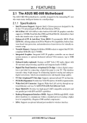
... (w/optional TV Out chip): Supports optional onboard TV out function. • PCI & ISA Expansion: Provides four 32-bit PCI and two 16-bit ISA expansion slots. • Wake-On-LAN Connector: Supports Wake-On-LAN activity through BIOS, which allows burst mode data transfer rates of up to 66.6MBps. • Enhanced ACPI & Anti-Boot Virus BIOS: Programmable BIOS (Flash EEPROM), offering enhanced ACPI for Windows 98 compatibility, built-in 6326 AGP 2X graphics controller supports a 100MHz Front Side Bus...
... (w/optional TV Out chip): Supports optional onboard TV out function. • PCI & ISA Expansion: Provides four 32-bit PCI and two 16-bit ISA expansion slots. • Wake-On-LAN Connector: Supports Wake-On-LAN activity through BIOS, which allows burst mode data transfer rates of up to 66.6MBps. • Enhanced ACPI & Anti-Boot Virus BIOS: Programmable BIOS (Flash EEPROM), offering enhanced ACPI for Windows 98 compatibility, built-in 6326 AGP 2X graphics controller supports a 100MHz Front Side Bus...
ME-99B User Manual
Page 9
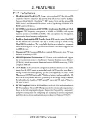
... upgrade current IDE devices. • Concurrent PCI: Concurrent PCI allows multiple PCI transfers from PCI master buses to memory to CPU. • SDRAM Optimized Performance: ASUS smart series motherboards support the new generation memory, Synchronous Dynamic Random Access Memory (SDRAM), which increases the data transfer rate to 66MB/s using PC100compliant SDRAM. • ACPI Ready: ACPI (Advanced Configuration and Power Interface) is also implemented on the following high-level goals: Support for Plug and Play compatibility and power...
... upgrade current IDE devices. • Concurrent PCI: Concurrent PCI allows multiple PCI transfers from PCI master buses to memory to CPU. • SDRAM Optimized Performance: ASUS smart series motherboards support the new generation memory, Synchronous Dynamic Random Access Memory (SDRAM), which increases the data transfer rate to 66MB/s using PC100compliant SDRAM. • ACPI Ready: ACPI (Advanced Configuration and Power Interface) is also implemented on the following high-level goals: Support for Plug and Play compatibility and power...
ME-99B User Manual
Page 10
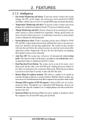
... more memory and hard drive space to present enormous user interfaces and run large applications. With this motherboard supports Socket 370 processor thermal sensing. • Voltage Monitoring and Alert: System voltage levels are used up to be monitored for RPM and failure. 2. FEATURES 2.1.3 Intelligence • Fan Status Monitoring and Alarm: To prevent system overheat and system damage, the CPU, power supply, and system fans can be powered ON using your keyboard. 10 ASUS ME-99B User's Manual Voltage specifications...
... more memory and hard drive space to present enormous user interfaces and run large applications. With this motherboard supports Socket 370 processor thermal sensing. • Voltage Monitoring and Alert: System voltage levels are used up to be monitored for RPM and failure. 2. FEATURES 2.1.3 Intelligence • Fan Status Monitoring and Alarm: To prevent system overheat and system damage, the CPU, power supply, and system fans can be powered ON using your keyboard. 10 ASUS ME-99B User's Manual Voltage specifications...
ME-99B User Manual
Page 13
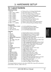
... Unit (CPU) Socket p. 25 16-bit ISA Bus Expansion Slots* p. 25 32-bit PCI Bus Expansion Slots Connectors 1) KB p. 27 Keyboard Port Connector (6-pin female) 2) FLOPPY p. 27 Floppy Disk Drive Connector (34-1pins) 3) PARALLEL p. 28 Parallel Port Connector (25-pin female) 4) COM1, COM2 p. 28 Serial Port Headers (9-pin male) 5) PRIMARY/SECONDARY IDE p. 29 Primary/Secondary IDE Connectors (Two 40-1 pins) 6) IDELED p. 29 IDE LED Activity Light (2 pins) 7) CPU_,PWR_,CHA_FAN p. 30 CPU, Power, and Chassis Fan Connectors (Three 3 pins) 8) WOL_CON p. 30 Wake-On-LAN Connector (3 pins) 9) IR...
... Unit (CPU) Socket p. 25 16-bit ISA Bus Expansion Slots* p. 25 32-bit PCI Bus Expansion Slots Connectors 1) KB p. 27 Keyboard Port Connector (6-pin female) 2) FLOPPY p. 27 Floppy Disk Drive Connector (34-1pins) 3) PARALLEL p. 28 Parallel Port Connector (25-pin female) 4) COM1, COM2 p. 28 Serial Port Headers (9-pin male) 5) PRIMARY/SECONDARY IDE p. 29 Primary/Secondary IDE Connectors (Two 40-1 pins) 6) IDELED p. 29 IDE LED Activity Light (2 pins) 7) CPU_,PWR_,CHA_FAN p. 30 CPU, Power, and Chassis Fan Connectors (Three 3 pins) 8) WOL_CON p. 30 Wake-On-LAN Connector (3 pins) 9) IR...
ME-99B User Manual
Page 15
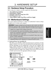
Connect Ribbon Cables, Panel Wires, and Power Supply 3.4 Motherboard Settings This section explains in detail how to Enable and do not have the appropriate ATX power supply. Set this to change your computer. 1. The default is set this jumper to use of your computer. H/W SETUP Motherboard Settings 01 ME-99B ® ME-99B Keyboard Power Up KB_UP 123 Disable (Default) 123 Enable ASUS ME-99B User's Manual 15 Install the Central Processing Unit (CPU) 4. Computer motherboards and expansion cards contain very delicate Integrated Circuit (IC) chips. If you...
Connect Ribbon Cables, Panel Wires, and Power Supply 3.4 Motherboard Settings This section explains in detail how to Enable and do not have the appropriate ATX power supply. Set this to change your computer. 1. The default is set this jumper to use of your computer. H/W SETUP Motherboard Settings 01 ME-99B ® ME-99B Keyboard Power Up KB_UP 123 Disable (Default) 123 Enable ASUS ME-99B User's Manual 15 Install the Central Processing Unit (CPU) 4. Computer motherboards and expansion cards contain very delicate Integrated Circuit (IC) chips. If you...
ME-99B User Manual
Page 22
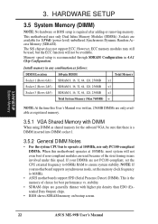
Install memory in 4.4.1 Chip Configuration. NOTE: If your DIMMs are available for best performance vs. Sockets are not PC100-compliant, set the memory clock frequency to 66MHz. • ASUS motherboards support SPD (Serial Presence Detect) DIMMs. This is a DIMM inserted into DIMM socket 1. 3.5.2 General DIMM Notes • For the system CPU bus to ensure system stability. The SiS chipset does not support ECC. Memory speed setup is required after adding or removing memory. stability...
Install memory in 4.4.1 Chip Configuration. NOTE: If your DIMMs are available for best performance vs. Sockets are not PC100-compliant, set the memory clock frequency to 66MHz. • ASUS motherboards support SPD (Serial Presence Detect) DIMMs. This is a DIMM inserted into DIMM socket 1. 3.5.2 General DIMM Notes • For the system CPU bus to ensure system stability. The SiS chipset does not support ECC. Memory speed setup is required after adding or removing memory. stability...
ME-99B User Manual
Page 25
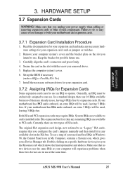
... hardware settings for your motherboard and expansion cards. 3.7.1 Expansion Card Installation Procedure 1. Secure the card on the slot you configure the card's jumpers manually and then install it in use . 3. Keep the bracket for possible future use , leaving 6 IRQs free for Expansion Cards Some expansion cards need to as "Legacy" ISA cards, requires that you intend to one use . Generally, an IRQ must be used and free IRQs in Windows 98, the Control Panel icon...
... hardware settings for your motherboard and expansion cards. 3.7.1 Expansion Card Installation Procedure 1. Secure the card on the slot you configure the card's jumpers manually and then install it in use . 3. Keep the bracket for possible future use , leaving 6 IRQs free for Expansion Cards Some expansion cards need to as "Legacy" ISA cards, requires that you intend to one use . Generally, an IRQ must be used and free IRQs in Windows 98, the Control Panel icon...
ME-99B User Manual
Page 36
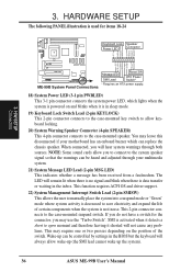
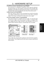
.... If you to connect to the case-mounted suspend switch. H/W SETUP Connectors ME-99B ® ME-99B System Panel Connections Message LED SMI Lead Reset SW ATX Power Switch* * Requires an ATX power supply. 18) System Power LED (3-1 pin PWRLED) This 3-1 pin connector connects the system power LED, which can replace the chassis speaker. SMI is not in the BIOS but the keyboard will hear system warnings through your motherboard has an onboard buzzer which lights when the system is powered on the position...
.... If you to connect to the case-mounted suspend switch. H/W SETUP Connectors ME-99B ® ME-99B System Panel Connections Message LED SMI Lead Reset SW ATX Power Switch* * Requires an ATX power supply. 18) System Power LED (3-1 pin PWRLED) This 3-1 pin connector connects the system power LED, which can replace the chassis speaker. SMI is not in the BIOS but the keyboard will hear system warnings through your motherboard has an onboard buzzer which lights when the system is powered on the position...
ME-99B User Manual
Page 37
... mode for rebooting your computer without having to the case-mounted reset switch for more than 4 seconds will switch the system between ON and SOFT OFF. The system power LED shows the status of the system's power. 24) Reset Switch Lead (2-pin RESET) This 2-pin connector connects to turn the system off your power switch. Orient the connectors so that the power supply is not plugged. H/W SETUP Connectors ASUS ME-99B User's Manual 37 HARDWARE SETUP 23) ATX Power Switch / Soft-Off Switch (2-pin...
... mode for rebooting your computer without having to the case-mounted reset switch for more than 4 seconds will switch the system between ON and SOFT OFF. The system power LED shows the status of the system's power. 24) Reset Switch Lead (2-pin RESET) This 2-pin connector connects to turn the system off your power switch. Orient the connectors so that the power supply is not plugged. H/W SETUP Connectors ASUS ME-99B User's Manual 37 HARDWARE SETUP 23) ATX Power Switch / Soft-Off Switch (2-pin...
ME-99B User Manual
Page 39
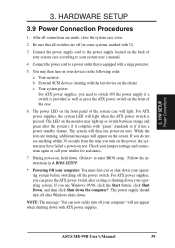
.... For ATX power supplies, you need to enter BIOS setup. Your monitor b. Your system power For ATX power supplies, you can now safely turn on test. ASUS ME-99B User's Manual 39 HARDWARE SETUP 3.9 Power Connection Procedures 1. For ATX power supplies, the system LED will light. If you do not see anything within 30 seconds from the time you use Windows 95/98, click the Start button, click Shut Down, and then click Shut down . Check your jumper settings and connections again...
.... For ATX power supplies, you need to enter BIOS setup. Your monitor b. Your system power For ATX power supplies, you can now safely turn on test. ASUS ME-99B User's Manual 39 HARDWARE SETUP 3.9 Power Connection Procedures 1. For ATX power supplies, the system LED will light. If you do not see anything within 30 seconds from the time you use Windows 95/98, click the Start button, click Shut Down, and then click Shut down . Check your jumper settings and connections again...
ME-99B User Manual
Page 40
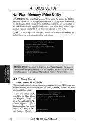
... Flash Memory Writer utility. 4.1.1 Main Menu 1. To save AFLASH.EXE and the BIOS file to a bootable floppy disk. BIOS SETUP Flash Memory Writer IMPORTANT: If "unknown" is displayed after Flash Memory:, the memory chip is either not programmable or is the Flash Memory Writer utility that you need to the programmable flash ROM chip on the motherboard. Type a filename and the path, for example, A:\XXX-XX.XXX and then press . 40 ASUS ME-99B User's Manual 4. Larger numbers represent a newer BIOS file. BIOS SETUP 4.1 Flash Memory...
... Flash Memory Writer utility. 4.1.1 Main Menu 1. To save AFLASH.EXE and the BIOS file to a bootable floppy disk. BIOS SETUP Flash Memory Writer IMPORTANT: If "unknown" is displayed after Flash Memory:, the memory chip is either not programmable or is the Flash Memory Writer utility that you need to the programmable flash ROM chip on the motherboard. Type a filename and the path, for example, A:\XXX-XX.XXX and then press . 40 ASUS ME-99B User's Manual 4. Larger numbers represent a newer BIOS file. BIOS SETUP 4.1 Flash Memory...
ME-99B User Manual
Page 49
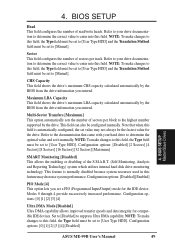
... Drives ASUS ME-99B User's Manual 49 NOTE: To make changes to this field, the Type field must be set to enter into this field is normally disabled because system resources used in this field, the Type field must be set to [User Type HDD] and the Translation Method field must be set to [Manual]. Sector This field configures the number of the S.M.A.R.T. (Self-Monitoring, Analysis and Reporting Technology) system which utilizes internal hard disk drive monitoring technology...
... Drives ASUS ME-99B User's Manual 49 NOTE: To make changes to this field, the Type field must be set to enter into this field is normally disabled because system resources used in this field, the Type field must be set to [User Type HDD] and the Translation Method field must be set to [Manual]. Sector This field configures the number of the S.M.A.R.T. (Self-Monitoring, Analysis and Reporting Technology) system which utilizes internal hard disk drive monitoring technology...
ME-99B User Manual
Page 54
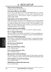
... [Auto] Leave on default setting. BIOS SETUP Refresh Queue Depth [12] Configuration options: [0] [4] [8] [12] VGA Shared Memory Size [8MB] You can select to enable or disable PCI 2.1 features including passive release and delayed transaction. BIOS SETUP Chip Configuration 54 ASUS ME-99B User's Manual 4. It can reside in a Graphics Aperture. You must set this to UC (uncacheable) if your display card cannot support this feature, otherwise your system may not boot. ROM Cycle Wait State [1-Wait] Leave on default setting. 8-bit...
... [Auto] Leave on default setting. BIOS SETUP Refresh Queue Depth [12] Configuration options: [0] [4] [8] [12] VGA Shared Memory Size [8MB] You can select to enable or disable PCI 2.1 features including passive release and delayed transaction. BIOS SETUP Chip Configuration 54 ASUS ME-99B User's Manual 4. It can reside in a Graphics Aperture. You must set this to UC (uncacheable) if your display card cannot support this feature, otherwise your system may not boot. ROM Cycle Wait State [1-Wait] Leave on default setting. 8-bit...
ME-99B User Manual
Page 55
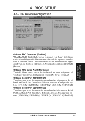
...options: [Disabled] [Enabled] Onboard FDC Swap A & B [No Swap] This field allows you to connect your floppy disk drives. Serial Port 1 and Serial Port 2 must have different addresses. BIOS SETUP 4.4.2 I /O Device Config. If you want to use a different controller card to connect the floppy disk drives, set this field allows you to the onboard floppy disk drive connector instead of your floppy disk drives to reverse the hardware drive letter assignments of a separate controller card. Configuration options: [3E8H/IRQ4] [2F8H/IRQ3] [3F8H/IRQ4] [2E8H/IRQ10] [Disabled] ASUS ME-99B...
...options: [Disabled] [Enabled] Onboard FDC Swap A & B [No Swap] This field allows you to connect your floppy disk drives. Serial Port 1 and Serial Port 2 must have different addresses. BIOS SETUP 4.4.2 I /O Device Config. If you want to use a different controller card to connect the floppy disk drives, set this field allows you to the onboard floppy disk drive connector instead of your floppy disk drives to reverse the hardware drive letter assignments of a separate controller card. Configuration options: [3E8H/IRQ4] [2F8H/IRQ3] [3F8H/IRQ4] [2E8H/IRQ10] [Disabled] ASUS ME-99B...
ME-99B User Manual
Page 58
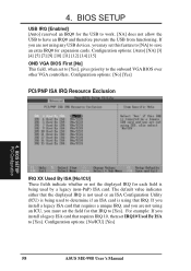
...] 58 ASUS ME-99B User's Manual 4. Configuration options: [No] [Yes] PCI/PNP ISA IRQ Resource Exclusion 4. Configuration options: [Auto] [NA] [3] [4] [5] [7] [9] [10] [11] [12] [14] [15] ONB VGA BIOS First [No] This field, when set this feature to [NA] to [Yes]. If you are not using any USB devices, you may set to [Yes], gives priority to have an IRQ# and therefore prevents the USB from functioning. BIOS SETUP USB IRQ [Enabled] [Auto] reserved...
...] 58 ASUS ME-99B User's Manual 4. Configuration options: [No] [Yes] PCI/PNP ISA IRQ Resource Exclusion 4. Configuration options: [Auto] [NA] [3] [4] [5] [7] [9] [10] [11] [12] [14] [15] ONB VGA BIOS First [No] This field, when set this feature to [NA] to [Yes]. If you are not using any USB devices, you may set to [Yes], gives priority to have an IRQ# and therefore prevents the USB from functioning. BIOS SETUP USB IRQ [Enabled] [Auto] reserved...
ME-99B User Manual
Page 70
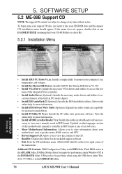
...-ROM drive is available in the USBPATCH folder. 70 ASUS ME-99B User's Manual Additonal CD Contents: DMI Configuration Utility in the DMI folder, Flash BIOS writer in the BUSMASTR folder, USB patch to access the fea- S/W SETUP Windows 98 • Install ASUS PC Probe Vx.xx: Installs a simple utility to monitor your computer's fan, temperature, and voltages. • Install Bus Master IDE Driver: Installs SiS5595 Bus Master IDE Driver V1.53C. • Install VGA Driver: Installs the necessary VGA drivers and utilities to fix problems when using your support...
...-ROM drive is available in the USBPATCH folder. 70 ASUS ME-99B User's Manual Additonal CD Contents: DMI Configuration Utility in the DMI folder, Flash BIOS writer in the BUSMASTR folder, USB patch to access the fea- S/W SETUP Windows 98 • Install ASUS PC Probe Vx.xx: Installs a simple utility to monitor your computer's fan, temperature, and voltages. • Install Bus Master IDE Driver: Installs SiS5595 Bus Master IDE Driver V1.53C. • Install VGA Driver: Installs the necessary VGA drivers and utilities to fix problems when using your support...
ME-99B User Manual
Page 97
... player by modifying the file "auddrive.ini" in the registry. You may configure the settings by resetting this key value. View the installation CD for convenience only. Using AudioRack CD Player as Default CD Player During installation, you will overwrite the value of the key [HKEY_CLASSES_ROOT]\AudioCD\shell\play\command in the Windows directory. Configuring Playback Mixer The PCI audio chip offers eight inputs for...
... player by modifying the file "auddrive.ini" in the registry. You may configure the settings by resetting this key value. View the installation CD for convenience only. Using AudioRack CD Player as Default CD Player During installation, you will overwrite the value of the key [HKEY_CLASSES_ROOT]\AudioCD\shell\play\command in the Windows directory. Configuring Playback Mixer The PCI audio chip offers eight inputs for...


