
User Manual
Page 3
Contents Notices...vi Safety information vii About this guide vii P8H61-M2 series specifications summary ix Chapter 1 Product introduction 1.1 Before you proceed 1-1 1.2 Motherboard overview 1-2 1.2.1 Motherboard layout 1-2 1.2.2 Layout contents 1-2 1.3 Central Processing Unit (CPU 1-3 1.4 System memory 1-3 1.4.1 Overview 1-3 1.4.2 Memory configurations 1-4 1.5 Expansion slots 1-7 ...16 Chapter 2 BIOS information 2.1 Managing and updating your BIOS 2-1 2.1.1 ASUS Update utility 2-1 2.1.2 ASUS EZ Flash 2 2-2 2.1.3 ASUS CrashFree BIOS 3 utility 2-3 2.1.4 ASUS BIOS Updater 2-4 iii
Contents Notices...vi Safety information vii About this guide vii P8H61-M2 series specifications summary ix Chapter 1 Product introduction 1.1 Before you proceed 1-1 1.2 Motherboard overview 1-2 1.2.1 Motherboard layout 1-2 1.2.2 Layout contents 1-2 1.3 Central Processing Unit (CPU 1-3 1.4 System memory 1-3 1.4.1 Overview 1-3 1.4.2 Memory configurations 1-4 1.5 Expansion slots 1-7 ...16 Chapter 2 BIOS information 2.1 Managing and updating your BIOS 2-1 2.1.1 ASUS Update utility 2-1 2.1.2 ASUS EZ Flash 2 2-2 2.1.3 ASUS CrashFree BIOS 3 utility 2-3 2.1.4 ASUS BIOS Updater 2-4 iii

User Manual
Page 6
... • Connect the equipment to an outlet on a circuit different from digital apparatus set out in our products at ASUS REACH website at http://csr.asus.com/english/REACH.htm. This equipment has been tested and found to comply with Part 15 of the FCC Rules. ...Restriction of Chemicals) regulatory framework, we published the chemical substances in the Radio Interference Regulations of the Canadian Department of Communications. If this unit not expressly approved by one or more of Communications Statement This digital apparatus does not exceed the Class B limits for radio noise emissions...
... • Connect the equipment to an outlet on a circuit different from digital apparatus set out in our products at ASUS REACH website at http://csr.asus.com/english/REACH.htm. This equipment has been tested and found to comply with Part 15 of the FCC Rules. ...Restriction of Chemicals) regulatory framework, we published the chemical substances in the Radio Interference Regulations of the Canadian Department of Communications. If this unit not expressly approved by one or more of Communications Statement This digital apparatus does not exceed the Class B limits for radio noise emissions...
User Manual
Page 15
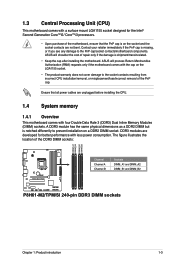
... DIMM_B2 P8H61-M2/TPM/SI Channel Channel A Channel B Sockets DIMM_A1 and DIMM_A2 DIMM_B1 and DIMM_B2 P8H61-M2/TPM/SI 240-pin DDR3 DIMM sockets Chapter 1: Product introduction 1-3 Ensure that the PnP cap is shipment/transit-related. • Keep the cap after installing the motherboard. ASUS will ... 1.4.1 Overview This motherboard comes with four Double Data Rate 3 (DDR3) Dual Inline Memory Modules (DIMM) sockets. 1.3 Central Processing Unit (CPU) This motherboard comes with a surface mount LGA1155 socket designed for the Intel® Second Generation Core™i5/ Core™...
... DIMM_B2 P8H61-M2/TPM/SI Channel Channel A Channel B Sockets DIMM_A1 and DIMM_A2 DIMM_B1 and DIMM_B2 P8H61-M2/TPM/SI 240-pin DDR3 DIMM sockets Chapter 1: Product introduction 1-3 Ensure that the PnP cap is shipment/transit-related. • Keep the cap after installing the motherboard. ASUS will ... 1.4.1 Overview This motherboard comes with four Double Data Rate 3 (DDR3) Dual Inline Memory Modules (DIMM) sockets. 1.3 Central Processing Unit (CPU) This motherboard comes with a surface mount LGA1155 socket designed for the Intel® Second Generation Core™i5/ Core™...

User Manual
Page 19
... the expansion card, read the documentation that you intend to install expansion cards. Install the software drivers for information on the slot. 5. Remove the system unit cover (if your motherboard is completely seated on BIOS setup. 2. Keep the screw for the card. 2. Assign an IRQ to the chassis with the PCI...
... the expansion card, read the documentation that you intend to install expansion cards. Install the software drivers for information on the slot. 5. Remove the system unit cover (if your motherboard is completely seated on BIOS setup. 2. Keep the screw for the card. 2. Assign an IRQ to the chassis with the PCI...
User Manual
Page 22
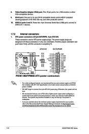
..., 4-pin ATX12V) These connectors are designed to install additional devices. The power supply plugs are for details. 1-10 ASUS P8H61-M2 Series ATX12V EATXPWR +12V DC +12V DC P8H61-M2/TPM/SI GND GND +3 Volts +12 Volts +12 Volts +5V Standby Power OK PIN 1 GND +5 Volts GND +5 Volts... +5 Volts +5 Volts +5 Volts -5 Volts GND GND GND PSON# GND -12 Volts +3 Volts P8H61-M2/TPM/SI ATX power connectors • For a fully configured system, we recommend that you use a power supply unit (PSU) that you use a PSU with a higher power output when configuring a system with ATX ...
..., 4-pin ATX12V) These connectors are designed to install additional devices. The power supply plugs are for details. 1-10 ASUS P8H61-M2 Series ATX12V EATXPWR +12V DC +12V DC P8H61-M2/TPM/SI GND GND +3 Volts +12 Volts +12 Volts +5V Standby Power OK PIN 1 GND +5 Volts GND +5 Volts... +5 Volts +5 Volts +5 Volts -5 Volts GND GND GND PSON# GND -12 Volts +3 Volts P8H61-M2/TPM/SI ATX power connectors • For a fully configured system, we recommend that you use a power supply unit (PSU) that you use a PSU with a higher power output when configuring a system with ATX ...


