
User Guide
Page 4
... information 2-23 2.12.1 Voltage selector 2-23 2.12.2 Power supply specifications 2-24 2.13 Connecting devices 2-25 Chapter 3: Starting up 3.1 Installing an operating system 3-2 3.2 Powering up 3-2 3.3 Using the system 3-2 3.3.1 CompactFlash card slot 3-2 3.3.2 Storage card slot 3-3 3.3.3 Optical drive 3-3 3.4 Support CD information 3-4 3.4.1 Running the support CD 3-4 3.4.2 Drivers menu 3-4 3.4.3 Utilities 3-5 3.4.4 ASUS contact information 3-6 3.4.5 Other information 3-7 Chapter 4: Motherboard information...
... information 2-23 2.12.1 Voltage selector 2-23 2.12.2 Power supply specifications 2-24 2.13 Connecting devices 2-25 Chapter 3: Starting up 3.1 Installing an operating system 3-2 3.2 Powering up 3-2 3.3 Using the system 3-2 3.3.1 CompactFlash card slot 3-2 3.3.2 Storage card slot 3-3 3.3.3 Optical drive 3-3 3.4 Support CD information 3-4 3.4.1 Running the support CD 3-4 3.4.2 Drivers menu 3-4 3.4.3 Utilities 3-5 3.4.4 ASUS contact information 3-6 3.4.5 Other information 3-7 Chapter 4: Motherboard information...

User Guide
Page 5
Table of contents Chapter 5: BIOS setup 5.1 Managing and updating your BIOS 5-2 5.1.1 ASUS EZ Flash utility 5-2 5.1.2 Recovering the BIOS with CrashFree BIOS 2 ..... 5-3 5.1.3 ASUS Update 5-5 5.2 BIOS Setup program 5-7 5.2.1 BIOS menu bar 5-8 5.2.2 Legend bar 5-8 5.3...Menu 5-13 5.4.1 CPU configuration 5-13 5.4.2 Chipset configuration 5-14 5.4.3 PCIPnP 5-15 5.4.4 Onboard device configuration 5-16 5.4.5 USB configuration 5-18 5.5 Power menu 5-19 5.5.1 APM configuration 5-20 5.5.2 Hardware Monitor 5-22 5.6 Boot menu5-23 5.6.1 Boot device priority 5-23 5.6.2 Removable drives 5-24 ...
Table of contents Chapter 5: BIOS setup 5.1 Managing and updating your BIOS 5-2 5.1.1 ASUS EZ Flash utility 5-2 5.1.2 Recovering the BIOS with CrashFree BIOS 2 ..... 5-3 5.1.3 ASUS Update 5-5 5.2 BIOS Setup program 5-7 5.2.1 BIOS menu bar 5-8 5.2.2 Legend bar 5-8 5.3...Menu 5-13 5.4.1 CPU configuration 5-13 5.4.2 Chipset configuration 5-14 5.4.3 PCIPnP 5-15 5.4.4 Onboard device configuration 5-16 5.4.5 USB configuration 5-18 5.5 Power menu 5-19 5.5.1 APM configuration 5-20 5.5.2 Hardware Monitor 5-22 5.6 Boot menu5-23 5.6.1 Boot device priority 5-23 5.6.2 Removable drives 5-24 ...

User Guide
Page 7
... with the package. • Before using the product, make sure all cables are correctly connected and the power cables are connected. • If the power supply is incorrectly replaced. Entsorgung gebrauchter Batterien nach Angaben des Herstellers. Lithium-Ion Battery Warning CAUTION: Danger of... service technician or your retailer. Operation safety • Before installing devices into the system, carefully read all the documentation that the power cables for the devices are unplugged before the signal cables are not damaged. Place the product on a stable surface. • If...
... with the package. • Before using the product, make sure all cables are correctly connected and the power cables are connected. • If the power supply is incorrectly replaced. Entsorgung gebrauchter Batterien nach Angaben des Herstellers. Lithium-Ion Battery Warning CAUTION: Danger of... service technician or your retailer. Operation safety • Before installing devices into the system, carefully read all the documentation that the power cables for the devices are unplugged before the signal cables are not damaged. Place the product on a stable surface. • If...

User Guide
Page 8
Chapter 3: Starting up This chapter helps you power up the system and install drivers and utilities from the support CD. 4. Chapter 4: Motherboard information This chapter gives information about the ASUS Book size barebone system. viii This guide is organized This guide contains the ...this guide Audience This guide provides general information and installation instructions about the motherboard that comes with hardware knowledge of the ASUS Book size barebone system. This chapter includes the motherboard layout, jumper settings, and connector locations. 5. The chapter lists...
Chapter 3: Starting up This chapter helps you power up the system and install drivers and utilities from the support CD. 4. Chapter 4: Motherboard information This chapter gives information about the ASUS Book size barebone system. viii This guide is organized This guide contains the ...this guide Audience This guide provides general information and installation instructions about the motherboard that comes with hardware knowledge of the ASUS Book size barebone system. This chapter includes the motherboard layout, jumper settings, and connector locations. 5. The chapter lists...

User Guide
Page 10
... or missing, contact your book size barebone system package for the following items. 1. ASUS book size barebone system with: • ASUS motherboard • CPU fan and heatsink assembly • CompactFlash card reader • 3-in-1 storage card reader • PCI riser card • 250W power supply unit 2. System package contents Check your retailer immediately.
... or missing, contact your book size barebone system package for the following items. 1. ASUS book size barebone system with: • ASUS motherboard • CPU fan and heatsink assembly • CompactFlash card reader • 3-in-1 storage card reader • PCI riser card • 250W power supply unit 2. System package contents Check your retailer immediately.

User Guide
Page 12
...stand. The foot stand allows you eject the loading tray. 2. See page 2-21 for choosing the ASUS book size barebone system! This system features a complete array of the ASUS book size barebone system makes it an ideal solution for your multimedia and computing needs. 1.2 Front panel...built on . 6. Press this 4 button to turn the system on ASUS technology and innovation. This LED lights up when data is the ASUS motherboard that the system is a union of the optical drive. 5 3. Power LED . The ASUS book size barebone system is ON. 7. Inside the elegant casing is ...
...stand. The foot stand allows you eject the loading tray. 2. See page 2-21 for choosing the ASUS book size barebone system! This system features a complete array of the ASUS book size barebone system makes it an ideal solution for your multimedia and computing needs. 1.2 Front panel...built on . 6. Press this 4 button to turn the system on ASUS technology and innovation. This LED lights up when data is the ASUS motherboard that the system is a union of the optical drive. 5 3. Power LED . The ASUS book size barebone system is ON. 7. Inside the elegant casing is ...

User Guide
Page 14
...This port 9 connects a video cassette recorder, camcorder, or television with serial specification. 10. This green 6-pin connector is a 7 250W power supply unit. 10 8 3. This port allows connection to select the appropriate voltage supply in 3 your area. USB 2.0 ports 2.0. These ...PCI-compliant cards. 9. PS/2 mouse port . 1.4 Rear panel The system rear panel includes the power socket and several I/O ports that conforms with S-Video interface. 4. Power supply unit. DVI-D port. This port connects a flat panel or LCD display. 12. This port...
...This port 9 connects a video cassette recorder, camcorder, or television with serial specification. 10. This green 6-pin connector is a 7 250W power supply unit. 10 8 3. This port allows connection to select the appropriate voltage supply in 3 your area. USB 2.0 ports 2.0. These ...PCI-compliant cards. 9. PS/2 mouse port . 1.4 Rear panel The system rear panel includes the power socket and several I/O ports that conforms with S-Video interface. 4. Power supply unit. DVI-D port. This port connects a flat panel or LCD display. 12. This port...

User Guide
Page 15
... This Line In (light blue) port connects a tape player or other audio sources. The functions of this port becomes Front Speaker Out. 16. ASUS Pundit P1-PH1 system 1-5 Microphone port . Line Out port . In 6-channel mode, the function of the Line Out (lime), Line In (blue), and... Microphone (pink) ports change when you select the 4-channel or 6-channel audio configuration as shown in the table below. Power socket. This Microphone (pink) port connects a microphone. Audio ports function variation Port Blue Lime Pink Headphone/2-Channel Line In Line Out Mic...
... This Line In (light blue) port connects a tape player or other audio sources. The functions of this port becomes Front Speaker Out. 16. ASUS Pundit P1-PH1 system 1-5 Microphone port . Line Out port . In 6-channel mode, the function of the Line Out (lime), Line In (blue), and... Microphone (pink) ports change when you select the 4-channel or 6-channel audio configuration as shown in the table below. Power socket. This Microphone (pink) port connects a microphone. Audio ports function variation Port Blue Lime Pink Headphone/2-Channel Line In Line Out Mic...

User Guide
Page 16
... for instructions on a flat, stable surface. 275mm 91mm 357mm 1-6 Chapter 1: System introduction ASUS motherboard 4. Storage drive assembly 2. DIMM sockets 6. Foot stand 1.6 System dimension The ASUS booksize barebone system is the internal view of the system when you remove the cover. Power supply unit 5. 1.5 Internal components The illustration below is ergonomically designed to Chapter...
... for instructions on a flat, stable surface. 275mm 91mm 357mm 1-6 Chapter 1: System introduction ASUS motherboard 4. Storage drive assembly 2. DIMM sockets 6. Foot stand 1.6 System dimension The ASUS booksize barebone system is the internal view of the system when you remove the cover. Power supply unit 5. 1.5 Internal components The illustration below is ergonomically designed to Chapter...

User Guide
Page 18
... into the system. • Use a grounded wrist strap or touch a safely grounded object or to a metal object, such as the power supply case, before installing any component, place it on them due to static electricity. • Hold components by the edges to install 1. Unplug... the power cable from the power outlet and make sure that you have all the components that came with an onboard standby power LED. SB_PWR ON Standby Power OFF Powered Off ® Onboard LED 2-2 Chapter 2: Basic installation The motherboard comes...
... into the system. • Use a grounded wrist strap or touch a safely grounded object or to a metal object, such as the power supply case, before installing any component, place it on them due to static electricity. • Hold components by the edges to install 1. Unplug... the power cable from the power outlet and make sure that you have all the components that came with an onboard standby power LED. SB_PWR ON Standby Power OFF Powered Off ® Onboard LED 2-2 Chapter 2: Basic installation The motherboard comes...

User Guide
Page 20
... aside. Lift the front cover hooks outward until its hooks are released from the chassis. 2. If your system comes with a preinstalled optical drive, disconnect the power, audio, and IDE plugs at the back of the drive before lifting the storage drive assembly. 2. To remove the front cover and storage drive assembly...
... aside. Lift the front cover hooks outward until its hooks are released from the chassis. 2. If your system comes with a preinstalled optical drive, disconnect the power, audio, and IDE plugs at the back of the drive before lifting the storage drive assembly. 2. To remove the front cover and storage drive assembly...

User Guide
Page 24
... (cross) screwdriver just enough to attach the heatsink to completely secure the heatsink. 3. Position the CPU fan and heatsink assembly on the motherboard. ® Fan power connector CPU_FAN Rotation +12V GND 2-8 Chapter 2: Basic installation 2.6.3 Reinstalling the CPU fan and heatsink assembly To reinstall the CPU fan and heatsink assembly: 1. When the...
... (cross) screwdriver just enough to attach the heatsink to completely secure the heatsink. 3. Position the CPU fan and heatsink assembly on the motherboard. ® Fan power connector CPU_FAN Rotation +12V GND 2-8 Chapter 2: Basic installation 2.6.3 Reinstalling the CPU fan and heatsink assembly To reinstall the CPU fan and heatsink assembly: 1. When the...

User Guide
Page 27
... and the components. • Reinstall the CPU fan and heatsink assembly before adding or removing DIMMs or other system components. ASUS Pundit P1-PH1 system 2-11 2.7.4 Installing a DIMM • Make sure to unplug the power supply before installing the DIMM(s) to avoid damaging the retaining clips of the DIMM sockets. Align a DIMM on how...
... and the components. • Reinstall the CPU fan and heatsink assembly before adding or removing DIMMs or other system components. ASUS Pundit P1-PH1 system 2-11 2.7.4 Installing a DIMM • Make sure to unplug the power supply before installing the DIMM(s) to avoid damaging the retaining clips of the DIMM sockets. Align a DIMM on how...

User Guide
Page 29
Failure to do so may need to install PCI cards to unplug the power cord before adding or removing expansion cards. The following figure shows a LAN card installed on a PCI slot. 2.8.2 PCI card installation To install a PCI card: 1. 2.8 Installing .... The system motherboard has one PCI slot with a preinstalled PCI riser assembly that comply with PCI specifications. Make sure to the system. PCI riser assembly ASUS Pundit P1-PH1 system 2-13 Slightly lift the PCI riser assembly until it disengages from the chassis.
Failure to do so may need to install PCI cards to unplug the power cord before adding or removing expansion cards. The following figure shows a LAN card installed on a PCI slot. 2.8.2 PCI card installation To install a PCI card: 1. 2.8 Installing .... The system motherboard has one PCI slot with a preinstalled PCI riser assembly that comply with PCI specifications. Make sure to the system. PCI riser assembly ASUS Pundit P1-PH1 system 2-13 Slightly lift the PCI riser assembly until it disengages from the chassis.
User Guide
Page 32
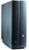
... install an IDE hard disk drive and optical drive: 1. Secure the storage drive assembly with two screws on how to the chassis. 7. Connect the 4-pin power plugs to the 5.25-inch bay, then secure it in the storage drive assembly. Configure your hard disk drive as a Master device. Insert the optical... drive upside down to the hard disk drive. 5. Turn the storage drive assembly, insert the hard disk drive upside down to the power connectors at the back of the drives. 6.
... install an IDE hard disk drive and optical drive: 1. Secure the storage drive assembly with two screws on how to the chassis. 7. Connect the 4-pin power plugs to the 5.25-inch bay, then secure it in the storage drive assembly. Configure your hard disk drive as a Master device. Insert the optical... drive upside down to the hard disk drive. 5. Turn the storage drive assembly, insert the hard disk drive upside down to the power connectors at the back of the drives. 6.

User Guide
Page 33
... at the back of the Serial ATA cable drive, then connect the other end to the 4-pin (male) power connector at the back of the drive. 15-pin 4-pin (male) Serial ATA power cable ASUS Pundit P1-PH1 system 2-17 See page 4-7 for the location of the previous section. 2. For Serial ATA HDDs with a 4-pin...
... at the back of the Serial ATA cable drive, then connect the other end to the 4-pin (male) power connector at the back of the drive. 15-pin 4-pin (male) Serial ATA power cable ASUS Pundit P1-PH1 system 2-17 See page 4-7 for the location of the previous section. 2. For Serial ATA HDDs with a 4-pin...

User Guide
Page 39
...area is 100-127V, set the switch to 115V. ASUS Pundit P1-PH1 system 2-23 Setting the switch to the voltage supply in a 230V environment will seriously damage the system! 2.12 Power supply unit information The system comes with a 250W power supply unit (PSU). 2.12.1 Voltage selector The PSU... has a 115V/230V voltage selector switch located beside the power socket. Use this switch to select the appropriate voltage ...
...area is 100-127V, set the switch to 115V. ASUS Pundit P1-PH1 system 2-23 Setting the switch to the voltage supply in a 230V environment will seriously damage the system! 2.12 Power supply unit information The system comes with a 250W power supply unit (PSU). 2.12.1 Voltage selector The PSU... has a 115V/230V voltage selector switch located beside the power socket. Use this switch to select the appropriate voltage ...

User Guide
Page 40
...120mVp-p 120mVp-p 50mVp-p 50mVp-p Over-Voltage Protection (OVP) Output Voltage +5V +3.3V +12V +5VSB Maximum Voltage 6.5V 4.6V 15.5V 7V The power supply will shut down or automatically recover when the fault condition is removed 2-24 Chapter 2: Basic installation at input 115Vac/230Vac and output full load...75W to 100A warm start. at 230Vac, full load 65% min. at 115Vac 4A max. continue power.) Peak inrush current shall be limited to max. 2.12.2 Power supply specifications Input Characteristics Input Voltage Range Range 1 Range 2 Input Frequency Range Maximum Input ac Current ...
...120mVp-p 120mVp-p 50mVp-p 50mVp-p Over-Voltage Protection (OVP) Output Voltage +5V +3.3V +12V +5VSB Maximum Voltage 6.5V 4.6V 15.5V 7V The power supply will shut down or automatically recover when the fault condition is removed 2-24 Chapter 2: Basic installation at input 115Vac/230Vac and output full load...75W to 100A warm start. at 230Vac, full load 65% min. at 115Vac 4A max. continue power.) Peak inrush current shall be limited to max. 2.12.2 Power supply specifications Input Characteristics Input Voltage Range Range 1 Range 2 Input Frequency Range Maximum Input ac Current ...
User Guide
Page 43
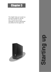
Chapter 3 This chapter helps you to install drivers and utilities from the support CD. Starting up and use the system for the first time. This part also provides information on how to power up
Chapter 3 This chapter helps you to install drivers and utilities from the support CD. Starting up and use the system for the first time. This part also provides information on how to power up

User Guide
Page 44
...located on the front panel. Refer to your book size barebone system. Press the system power button ( ) to use the setup procedures presented in this chapter for detailed information. 3.2 Powering up 3.1 Installing an operating system The ASUS book size barebone system supports Windows® 2000 / XP operating systems (OS). Because motherboard... install the latest OS version and corresponding updates so you can maximize the features of your OS documentation for general reference only. System power button 3.3 Using the system The following sections illustrate how to enter the OS.
...located on the front panel. Refer to your book size barebone system. Press the system power button ( ) to use the setup procedures presented in this chapter for detailed information. 3.2 Powering up 3.1 Installing an operating system The ASUS book size barebone system supports Windows® 2000 / XP operating systems (OS). Because motherboard... install the latest OS version and corresponding updates so you can maximize the features of your OS documentation for general reference only. System power button 3.3 Using the system The following sections illustrate how to enter the OS.