
User Guide
Page 4
... operating system 3-2 3.2 Powering up 3-2 3.3 Using the system 3-2 3.3.1 CompactFlash card slot 3-2 3.3.2 Storage card slot 3-3 3.3.3 Optical drive 3-3 3.4 Support CD information 3-4 3.4.1 Running the support CD 3-4 3.4.2 Drivers menu 3-4 3.4.3 Utilities 3-5 3.4.4 ASUS contact information 3-6 3.4.5 Other information 3-7 Chapter 4: Motherboard information 4.1 Introduction 4-2 4.2 Motherboard layout 4-2 4.3 Jumper 4-3 4.4 Internal connectors 4-4 iv
... operating system 3-2 3.2 Powering up 3-2 3.3 Using the system 3-2 3.3.1 CompactFlash card slot 3-2 3.3.2 Storage card slot 3-3 3.3.3 Optical drive 3-3 3.4 Support CD information 3-4 3.4.1 Running the support CD 3-4 3.4.2 Drivers menu 3-4 3.4.3 Utilities 3-5 3.4.4 ASUS contact information 3-6 3.4.5 Other information 3-7 Chapter 4: Motherboard information 4.1 Introduction 4-2 4.2 Motherboard layout 4-2 4.3 Jumper 4-3 4.4 Internal connectors 4-4 iv

User Guide
Page 8
...up This chapter helps you power up the system and install drivers and utilities from the support CD. 4. This chapter includes the motherboard layout, jumper settings, and connector locations. 5. viii Chapter 5: BIOS setup This chapter tells how to install components in the ...the system. Chapter 1: System introduction This chapter gives a general description of personal computers. Chapter 4: Motherboard information This chapter gives information about the ASUS Book size barebone system. How this guide Audience This guide provides general information and installation instructions about...
...up This chapter helps you power up the system and install drivers and utilities from the support CD. 4. This chapter includes the motherboard layout, jumper settings, and connector locations. 5. viii Chapter 5: BIOS setup This chapter tells how to install components in the ...the system. Chapter 1: System introduction This chapter gives a general description of personal computers. Chapter 4: Motherboard information This chapter gives information about the ASUS Book size barebone system. How this guide Audience This guide provides general information and installation instructions about...

User Guide
Page 10
... barebone system with: • ASUS motherboard • CPU fan and heatsink assembly • CompactFlash card reader • 3-in-1 storage card reader • PCI riser card • 250W power supply unit 2. CDs &#...
... barebone system with: • ASUS motherboard • CPU fan and heatsink assembly • CompactFlash card reader • 3-in-1 storage card reader • PCI riser card • 250W power supply unit 2. CDs &#...

User Guide
Page 12
... panel (external) The front panel includes the system and audio control buttons, 2 system LEDs, and LED panel. 3 1. Power button . The ASUS book size barebone system is a union of multimedia capabilities and seamless connectivity including dual display function, Fast Ethernet, 3-in a vertical position. Eject button... with up to the hard disk drive. 7 4. When lit, this 4 button to 2GB system memory. Inside the elegant casing is the ASUS motherboard that the system is being read 6 from or written to 800MHz front side bus (FSB), and up when data is ON. 7. Power ...
... panel (external) The front panel includes the system and audio control buttons, 2 system LEDs, and LED panel. 3 1. Power button . The ASUS book size barebone system is a union of multimedia capabilities and seamless connectivity including dual display function, Fast Ethernet, 3-in a vertical position. Eject button... with up to the hard disk drive. 7 4. When lit, this 4 button to 2GB system memory. Inside the elegant casing is the ASUS motherboard that the system is being read 6 from or written to 800MHz front side bus (FSB), and up when data is ON. 7. Power ...

User Guide
Page 16
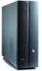
... unit 5. CPU fan and heatsink assembly 7. 1.5 Internal components The illustration below is ergonomically designed to fit and complement your reference. PCI riser 3. ASUS motherboard 4. Foot stand 1.6 System dimension The ASUS booksize barebone system is the internal view of the system when you remove the cover. The installed components are labeled for instructions on...
... unit 5. CPU fan and heatsink assembly 7. 1.5 Internal components The illustration below is ergonomically designed to fit and complement your reference. PCI riser 3. ASUS motherboard 4. Foot stand 1.6 System dimension The ASUS booksize barebone system is the internal view of the system when you remove the cover. The installed components are labeled for instructions on...

User Guide
Page 18
... on them. • Whenever you uninstall any system component. SB_PWR ON Standby Power OFF Powered Off ® Onboard LED 2-2 Chapter 2: Basic installation Expansion card(s) 4. The motherboard comes with the component. When lit, this LED indicates that the system is OFF before handling components to avoid damaging them due to static electricity...
... on them. • Whenever you uninstall any system component. SB_PWR ON Standby Power OFF Powered Off ® Onboard LED 2-2 Chapter 2: Basic installation Expansion card(s) 4. The motherboard comes with the component. When lit, this LED indicates that the system is OFF before handling components to avoid damaging them due to static electricity...

User Guide
Page 21
...to the CPU. • DO NOT replace the proprietary CPU fan and heatsink with a surface mount LGA775 socket designed for details on the motherboard. 2. ASUS Pundit P1-PH1 system 2-5 To remove the CPU fan and heatsink assembly: 1. Lift the CPU fan and heatsink assembly, then set aside. You must... fan and heatsink assembly before removing the CPU fan and heatsink assembly to remove the memory modules. 2.6 Installing a CPU The motherboard comes with other models. • Remove the memory modules first before installing a CPU. Loosen the CPU fan and heatsink assembly screws. 3.
...to the CPU. • DO NOT replace the proprietary CPU fan and heatsink with a surface mount LGA775 socket designed for details on the motherboard. 2. ASUS Pundit P1-PH1 system 2-5 To remove the CPU fan and heatsink assembly: 1. Lift the CPU fan and heatsink assembly, then set aside. You must... fan and heatsink assembly before removing the CPU fan and heatsink assembly to remove the memory modules. 2.6 Installing a CPU The motherboard comes with other models. • Remove the memory modules first before installing a CPU. Loosen the CPU fan and heatsink assembly screws. 3.

User Guide
Page 22
To prevent damage to the left . 2. Locate the 775-pin CPU socket on your thumb (A) and move it is facing towards you . Press the load lever with your left (B) until it to the socket pins, do not remove the PnP cap unless you are installing a CPU. 2-6 Chapter 2: Basic installation Retention tab A Load lever PnP Cap B This side of the socket box should face you and the load lever is on the motherboard. ® CPU Socket 775 Before installing the CPU, make sure that the socket box is released from the retention tab. 2.6.2 CPU installation To install the CPU: 1.
To prevent damage to the left . 2. Locate the 775-pin CPU socket on your thumb (A) and move it is facing towards you . Press the load lever with your left (B) until it to the socket pins, do not remove the PnP cap unless you are installing a CPU. 2-6 Chapter 2: Basic installation Retention tab A Load lever PnP Cap B This side of the socket box should face you and the load lever is on the motherboard. ® CPU Socket 775 Before installing the CPU, make sure that the socket box is released from the retention tab. 2.6.2 CPU installation To install the CPU: 1.

User Guide
Page 24
... heatsink. 3. 2.6.3 Reinstalling the CPU fan and heatsink assembly To reinstall the CPU fan and heatsink assembly: 1. Position the CPU fan and heatsink assembly on the motherboard. ® Fan power connector CPU_FAN Rotation +12V GND 2-8 Chapter 2: Basic installation Hold down the heatsink lightly and twist each of the installed CPU. 2. When the...
... heatsink. 3. 2.6.3 Reinstalling the CPU fan and heatsink assembly To reinstall the CPU fan and heatsink assembly: 1. Position the CPU fan and heatsink assembly on the motherboard. ® Fan power connector CPU_FAN Rotation +12V GND 2-8 Chapter 2: Basic installation Hold down the heatsink lightly and twist each of the installed CPU. 2. When the...

User Guide
Page 25
2.7 Installing memory modules 2.7.1 Overview The system motherboard has two DDR II DIMM sockets that you obtain memory modules from the same vendor. Refer to the illustration below for a list of the DIMM ..., 128MB, 256MB, 512MB, and 1GB DDR II DIMMs to 2GB non-ECC PC5300/4200/3200 DDR II SDRAM DIMMs. Each DIMM socket is double-sided. ASUS Pundit P1-PH1 system 2-9
2.7 Installing memory modules 2.7.1 Overview The system motherboard has two DDR II DIMM sockets that you obtain memory modules from the same vendor. Refer to the illustration below for a list of the DIMM ..., 128MB, 256MB, 512MB, and 1GB DDR II DIMMs to 2GB non-ECC PC5300/4200/3200 DDR II SDRAM DIMMs. Each DIMM socket is double-sided. ASUS Pundit P1-PH1 system 2-9

User Guide
Page 26
...-6E-E 5 Brand SAMSUNG SAMSUNG Kingston Hynix Hynix Hynix MICRON MICRON MICRON Infineon Infineon Infineon ELPIDA - Visit the ASUS website (www.asus.com) for use with this motherboard. ELPIDA SS/DS SS DS DS SS DS SS DS SS SS SS SS DS SS DS SS DIMM support...Y4 V V 4VB41D9CZM VV 4SB42D9CZM VV 5FB42D9DPN VV HYB18T512160AF-3S V V HYB18T512800AF3S V V HYB18T512800AF3S V V E5108AE-GE-E VV - Obtain DDR II DIMMs only from ASUS qualified vendors. VV E2508AB-GE-E VV A* : Supports one pair of modules inserted into eithor the blue slots or the black slots as one module inserted...
...-6E-E 5 Brand SAMSUNG SAMSUNG Kingston Hynix Hynix Hynix MICRON MICRON MICRON Infineon Infineon Infineon ELPIDA - Visit the ASUS website (www.asus.com) for use with this motherboard. ELPIDA SS/DS SS DS DS SS DS SS DS SS SS SS SS DS SS DS SS DIMM support...Y4 V V 4VB41D9CZM VV 4SB42D9CZM VV 5FB42D9DPN VV HYB18T512160AF-3S V V HYB18T512800AF3S V V HYB18T512800AF3S V V E5108AE-GE-E VV - Obtain DDR II DIMMs only from ASUS qualified vendors. VV E2508AB-GE-E VV A* : Supports one pair of modules inserted into eithor the blue slots or the black slots as one module inserted...

User Guide
Page 27
...DIMM sockets in only one direction. Align a DIMM on the socket such that it fits in the motherboard. 2. Failure to do so may cause severe damage to both the motherboard and the components. • Reinstall the CPU fan and heatsink assembly before installing the DIMM(s) to ...previous section for details on the socket. 4. DDR II DIMM notch Unlocked retaining clip Locked retaining clip A DDR II DIMM is properly seated. ASUS Pundit P1-PH1 system 2-11 2.7.4 Installing a DIMM • Make sure to avoid damaging the retaining clips of the DIMM sockets. Refer to avoid damaging...
...DIMM sockets in only one direction. Align a DIMM on the socket such that it fits in the motherboard. 2. Failure to do so may cause severe damage to both the motherboard and the components. • Reinstall the CPU fan and heatsink assembly before installing the DIMM(s) to ...previous section for details on the socket. 4. DDR II DIMM notch Unlocked retaining clip Locked retaining clip A DDR II DIMM is properly seated. ASUS Pundit P1-PH1 system 2-11 2.7.4 Installing a DIMM • Make sure to avoid damaging the retaining clips of the DIMM sockets. Refer to avoid damaging...

User Guide
Page 29
... injury and damage motherboard components. 2.8.1 PCI slots The PCI slots support PCI cards such as a LAN card, SCSI card, USB card, and other cards that comply with a preinstalled PCI riser assembly that supports two PCI cards. The system motherboard has one PCI slot with PCI specifications. PCI riser assembly ASUS Pundit P1-PH1 system 2-13...
... injury and damage motherboard components. 2.8.1 PCI slots The PCI slots support PCI cards such as a LAN card, SCSI card, USB card, and other cards that comply with a preinstalled PCI riser assembly that supports two PCI cards. The system motherboard has one PCI slot with PCI specifications. PCI riser assembly ASUS Pundit P1-PH1 system 2-13...

User Guide
Page 31
... -- -- shared -- F G H -- -- -- -- -- -- -- -- -- -- -- -- -- -- -- -- -- -- -- -- -- -- -- -- ASUS Pundit P1-PH1 system 2-15 shared -- -- -- shared -- Onboard SATA2 -- -- -- -- -- usedd When using a PCI card on BIOS setup. 2. IRQ assignments for the ... card by adjusting the software settings. 1. used -- -- -- Onboard 1394 controller -- -- -- -- -- Install the software drivers for this motherboard A B C D E PCI slot 1 used -- -- -- -- shared -- -- -- used 10* 5 IRQ Holder for PCI Steering ...
... -- -- shared -- F G H -- -- -- -- -- -- -- -- -- -- -- -- -- -- -- -- -- -- -- -- -- -- -- -- ASUS Pundit P1-PH1 system 2-15 shared -- -- -- shared -- Onboard SATA2 -- -- -- -- -- usedd When using a PCI card on BIOS setup. 2. IRQ assignments for the ... card by adjusting the software settings. 1. used -- -- -- Onboard 1394 controller -- -- -- -- -- Install the software drivers for this motherboard A B C D E PCI slot 1 used -- -- -- -- shared -- -- -- used 10* 5 IRQ Holder for PCI Steering ...

User Guide
Page 33
... the back of the drive. Follow steps 1-3 of the Serial ATA connector. 3. Connect the 15-pin SATA power plug to the SATA connector on the motherboard. For Serial ATA HDDs with a 4-pin power connector: Connect a 4-pin (female) power plug from the PSU to the connector at the back of the SATA...: 1. Connect one end of the supplied 7-pin SATA cable to the 4-pin (male) plug of the drive. 15-pin 4-pin (male) Serial ATA power cable ASUS Pundit P1-PH1 system 2-17 For Serial ATA HDDs without a 4-pin power connector: Use the supplied SATA power cable.
... the back of the drive. Follow steps 1-3 of the Serial ATA connector. 3. Connect the 15-pin SATA power plug to the SATA connector on the motherboard. For Serial ATA HDDs with a 4-pin power connector: Connect a 4-pin (female) power plug from the PSU to the connector at the back of the SATA...: 1. Connect one end of the supplied 7-pin SATA cable to the 4-pin (male) plug of the drive. 15-pin 4-pin (male) Serial ATA power cable ASUS Pundit P1-PH1 system 2-17 For Serial ATA HDDs without a 4-pin power connector: Use the supplied SATA power cable.

User Guide
Page 44
... 3-2 Chapter 3: Starting up The system power button is located on the front panel. 3.1 Installing an operating system The ASUS book size barebone system supports Windows® 2000 / XP operating systems (OS). Because motherboard settings and hardware options vary, use the storage card reader slots, and the optical drive. 3.3.1 CompactFlash card slot The...
... 3-2 Chapter 3: Starting up The system power button is located on the front panel. 3.1 Installing an operating system The ASUS book size barebone system supports Windows® 2000 / XP operating systems (OS). Because motherboard settings and hardware options vary, use the storage card reader slots, and the optical drive. 3.3.1 CompactFlash card slot The...

User Guide
Page 47
... alerts you on any detected problems. This utility helps you to install the Realtek LAN Driver. Realtek LAN Driver Click this item to update the motherboard BIOS and drivers. This utility requires an Internet connection either through a network or an Internet Service Provider (ISP). ASUS Pundit P1-PH1 system 3-5
... alerts you on any detected problems. This utility helps you to install the Realtek LAN Driver. Realtek LAN Driver Click this item to update the motherboard BIOS and drivers. This utility requires an Internet connection either through a network or an Internet Service Provider (ISP). ASUS Pundit P1-PH1 system 3-5

User Guide
Page 49
Click an icon to display the specified information. Browse this CD Displays the support CD contents in graphical format. ASUS Pundit P1-PH1 system 3-7 3.4.5 Other information The icons on the top right side of the screen give additional information on the motherboard and the contents of the motherboard. Motherboard info Displays the general specifications of the support CD.
Click an icon to display the specified information. Browse this CD Displays the support CD contents in graphical format. ASUS Pundit P1-PH1 system 3-7 3.4.5 Other information The icons on the top right side of the screen give additional information on the motherboard and the contents of the motherboard. Motherboard info Displays the general specifications of the support CD.

User Guide
Page 51
Motherboard info This chapter includes the motherboard layout, jumper settings, and connector locations. Chapter 4 This chapter gives information about the motherboard that comes with the system.
Motherboard info This chapter includes the motherboard layout, jumper settings, and connector locations. Chapter 4 This chapter gives information about the motherboard that comes with the system.

User Guide
Page 52
4.1 Introduction The ASUS motherboard comes already installed in the ASUS book size barebone system. This chapter provides technical information about the motherboard for future upgrades or system reconfiguration. 4.2 Motherboard layout PMC Flash CR2032 3V Lithium Cell CMOS Power CLRTC USB34 SB_PWR PANEL BUZZER RSTCON SMSC USB2227 CF_CON PRI_IDE VIA VT6307 SATA1 ATI SB450 3IN1_CON ... DDR2 DIMMA1 (64 bit,240-pin module) DDR2 DIMMB1 (64 bit,240-pin module) LGA775 ATX12V SPDIF_IN SPDIF_OUT IE1394_1 PWRSW IE1394_2 USB12 FP_AUDIO CPU_FAN 4-2 Chapter 4: Motherboard info
4.1 Introduction The ASUS motherboard comes already installed in the ASUS book size barebone system. This chapter provides technical information about the motherboard for future upgrades or system reconfiguration. 4.2 Motherboard layout PMC Flash CR2032 3V Lithium Cell CMOS Power CLRTC USB34 SB_PWR PANEL BUZZER RSTCON SMSC USB2227 CF_CON PRI_IDE VIA VT6307 SATA1 ATI SB450 3IN1_CON ... DDR2 DIMMA1 (64 bit,240-pin module) DDR2 DIMMB1 (64 bit,240-pin module) LGA775 ATX12V SPDIF_IN SPDIF_OUT IE1394_1 PWRSW IE1394_2 USB12 FP_AUDIO CPU_FAN 4-2 Chapter 4: Motherboard info