
User Manual
Page 4
... of the ASUS TX97 Motherboard 11 III. Jumpers 14 Jumper Settings 15 Compatible Cyrix CPU Identification 17 2. Central Processing Unit (CPU 21 4. System Memory (DIMM 19 DIMM Memory Installation Procedures 20 3. Expansion Cards 22 Expansion Card Installation Procedure 22 Assigning IRQs for Expansion Cards 22 Assigning DMA Channels for ISA Cards 23 5. BIOS SOFTWARE 32 Support Software 32 Flash Memory Writer Utility 32 Main Menu 33 Advanced Features Menu 33 Managing & Updating your Motherboard's BIOS 34 6. CONTENTS I. External Connectors 24 Power Connection Procedures 31...
... of the ASUS TX97 Motherboard 11 III. Jumpers 14 Jumper Settings 15 Compatible Cyrix CPU Identification 17 2. Central Processing Unit (CPU 21 4. System Memory (DIMM 19 DIMM Memory Installation Procedures 20 3. Expansion Cards 22 Expansion Card Installation Procedure 22 Assigning IRQs for Expansion Cards 22 Assigning DMA Channels for ISA Cards 23 5. BIOS SOFTWARE 32 Support Software 32 Flash Memory Writer Utility 32 Main Menu 33 Advanced Features Menu 33 Managing & Updating your Motherboard's BIOS 34 6. CONTENTS I. External Connectors 24 Power Connection Procedures 31...

User Manual
Page 5
... the ASUS PCI-SC200 60 Terminator Requirements for SCSI Devices 60 Terminator Settings for the ASUS PCI-SC860 61 Terminator Settings for the ASUS PCI-SC200 61 SCSI ID Numbers for SCSI Devices 62 SCSI ID Priority 62 ASUS TX97 User's Manual 5 SUPPORT SOFTWARE 54 ASUS TX97 Motherboard Series Support CD 54 LANDesk Client Manager (LDCM 54 Desktop Management Interface (DMI 56 Introducing the ASUS DMI Configuration Utility 56 System Requirements 56 Using the ASUS DMI Configuration Utility 57...
... the ASUS PCI-SC200 60 Terminator Requirements for SCSI Devices 60 Terminator Settings for the ASUS PCI-SC860 61 Terminator Settings for the ASUS PCI-SC200 61 SCSI ID Numbers for SCSI Devices 62 SCSI ID Priority 62 ASUS TX97 User's Manual 5 SUPPORT SOFTWARE 54 ASUS TX97 Motherboard Series Support CD 54 LANDesk Client Manager (LDCM 54 Desktop Management Interface (DMI 56 Introducing the ASUS DMI Configuration Utility 56 System Requirements 56 Using the ASUS DMI Configuration Utility 57...

User Manual
Page 7
... This user's manual PS/2 mouse, USB, and IR cable with mounting bracket set (optional) ATX to AT Power Connector Adapter (optional) ASUS PCI-SC200 Fast-SCSI or PCI-SC860 Ultra-Fast SCSI card (optional) ASUS TX97 User's Manual 7 Features: Information and specifications concerning this manual is organized This manual is complete. The ASUS TX97 motherboard 2 serial port ribbon cables attached to a mounting bracket 1 parallel ribbon cable with mounting bracket 1 IDE ribbon cable 1 floppy ribbon cable Support Drivers and Utilities: • Flash Memory Writer utility to update the FLASH BIOS...
... This user's manual PS/2 mouse, USB, and IR cable with mounting bracket set (optional) ATX to AT Power Connector Adapter (optional) ASUS PCI-SC200 Fast-SCSI or PCI-SC860 Ultra-Fast SCSI card (optional) ASUS TX97 User's Manual 7 Features: Information and specifications concerning this manual is organized This manual is complete. The ASUS TX97 motherboard 2 serial port ribbon cables attached to a mounting bracket 1 parallel ribbon cable with mounting bracket 1 IDE ribbon cable 1 floppy ribbon cable Support Drivers and Utilities: • Flash Memory Writer utility to update the FLASH BIOS...

User Manual
Page 8
... ASUS TX97 Motherboard The ASUS TX97 is available for wireless connections. This motherboard: • Intel Chipset: Features Intel's 430TX PCIset with I /O: Provides two high-speed UART compatible serial ports and one PCI/MediaBus/ISA shared slot which allows the use of compatibility. (Requires DMI-enabled components.) (See section V) • PCI Bus Master IDE Controller: Comes with an onboard Ultra DMA/33 Bus Master IDE controller with EPP and ECP capabilities. FEATURES Features of hard drives, expansion cards, and other devices virtually...
... ASUS TX97 Motherboard The ASUS TX97 is available for wireless connections. This motherboard: • Intel Chipset: Features Intel's 430TX PCIset with I /O: Provides two high-speed UART compatible serial ports and one PCI/MediaBus/ISA shared slot which allows the use of compatibility. (Requires DMI-enabled components.) (See section V) • PCI Bus Master IDE Controller: Comes with an onboard Ultra DMA/33 Bus Master IDE controller with EPP and ECP capabilities. FEATURES Features of hard drives, expansion cards, and other devices virtually...

User Manual
Page 9
... system components, and 32-bit device drivers and installation procedures for its normal RPM range and alarm thresholds. • Temperature Monitoring and Alert - Each fan can be used. • PC '97 Compliant - II. FEATURES (TX97 Series) II. ASUS TX97 User's Manual 9 ASUS TX97 series of motherboards. ACPI (Advanced Configuration and Power Interface) is compatible with Intel 430TX PCIset improves IDE transfer rate using EDO memory to avoid any failures triggered by extremely high temperature. With these features implemented...
... system components, and 32-bit device drivers and installation procedures for its normal RPM range and alarm thresholds. • Temperature Monitoring and Alert - Each fan can be used. • PC '97 Compliant - II. FEATURES (TX97 Series) II. ASUS TX97 User's Manual 9 ASUS TX97 series of motherboards. ACPI (Advanced Configuration and Power Interface) is compatible with Intel 430TX PCIset improves IDE transfer rate using EDO memory to avoid any failures triggered by extremely high temperature. With these features implemented...

User Manual
Page 10
... more memory and hard drive space to critical motherboard components. A simple glimpse provides useful information to implement silent PC systems. • Dual Function Power Button (requires ATX power supply) - This will give the user information on storage media such as information providers. Through the way a particular LED illuminates, the user can be turned on storage media, but also clear BIOS data which is a important feature to the user. 10 ASUS TX97 User's Manual II...
... more memory and hard drive space to critical motherboard components. A simple glimpse provides useful information to implement silent PC systems. • Dual Function Power Button (requires ATX power supply) - This will give the user information on storage media such as information providers. Through the way a particular LED illuminates, the user can be turned on storage media, but also clear BIOS data which is a important feature to the user. 10 ASUS TX97 User's Manual II...

User Manual
Page 13
.../Clear Data) p. 17 CPU Voltage Selection p. 18 CPU External Clock (BUS) Frequency Selection p. 18 CPU:BUS Frequency Ratio Expansion Slots 1) DIMM Sockets 2) ZIF Socket 7 3) ISA Slots 4) PCI Slots p. 19 168-Pin SDRAM Memory Expansion Sockets p. 21 Central Processing Unit (CPU) Socket p. 22 16-bit ISA Bus Expansion Slots p. 22 32-bit PCI Bus Expansion Slots Connectors 1) KBCON 2) FLOPPY 3) PRINTER 4) COM1, COM2 5) FAN 6) CHASSIS 7) Primary / Second IDE 8) IDELED 9) POWER 10) TB LED (PANEL) 11) SMI (PANEL) 12) ATX PWR 13) RESET (PANEL) 14) KEYLOCK (PANEL) 15) SPEAKER (PANEL) 16) PS2MOUSE/USB...
.../Clear Data) p. 17 CPU Voltage Selection p. 18 CPU External Clock (BUS) Frequency Selection p. 18 CPU:BUS Frequency Ratio Expansion Slots 1) DIMM Sockets 2) ZIF Socket 7 3) ISA Slots 4) PCI Slots p. 19 168-Pin SDRAM Memory Expansion Sockets p. 21 Central Processing Unit (CPU) Socket p. 22 16-bit ISA Bus Expansion Slots p. 22 32-bit PCI Bus Expansion Slots Connectors 1) KBCON 2) FLOPPY 3) PRINTER 4) COM1, COM2 5) FAN 6) CHASSIS 7) Primary / Second IDE 8) IDELED 9) POWER 10) TB LED (PANEL) 11) SMI (PANEL) 12) ATX PWR 13) RESET (PANEL) 14) KEYLOCK (PANEL) 15) SPEAKER (PANEL) 16) PS2MOUSE/USB...
User Manual
Page 16
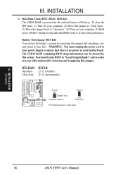
... "Operation," (4) Turn on your motherboard. The CMOS RAM containing BIOS setup information may be cleared by removing this jumper to "Clear Data," (3) Move the jumper back to pins 2&3. Battery Test Jumper (RTCLR) You can test the battery's current by this jumper. III. INSTALLATION (Jumpers) 16 ASUS TX97 User's Manual Real Time Clock (RTC) RAM (RTCLR) The CMOS RAM is no power to your computer, (5) Hold down during bootup and enter BIOS setup to "Load Setup Defaults" and re-enter any user information after removing and reapplying...
... "Operation," (4) Turn on your motherboard. The CMOS RAM containing BIOS setup information may be cleared by removing this jumper to "Clear Data," (3) Move the jumper back to pins 2&3. Battery Test Jumper (RTCLR) You can test the battery's current by this jumper. III. INSTALLATION (Jumpers) 16 ASUS TX97 User's Manual Real Time Clock (RTC) RAM (RTCLR) The CMOS RAM is no power to your computer, (5) Hold down during bootup and enter BIOS setup to "Load Setup Defaults" and re-enter any user information after removing and reapplying...
User Manual
Page 27
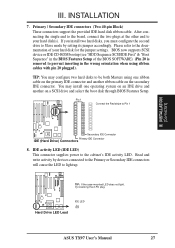
... IDE (Hard Drive) Connectors 8. BIOS now supports SCSI device or IDE CD-ROM bootup (see "HDD Sequence SCSI/IDE First" & "Boot Sequence" in the wrong orientation when using one operating system on an IDE drive and another ribbon cable on a SCSI drive and select the boot disk through BIOS Features Setup. IDE activity LED (IDE LED) This connector supplies power to the documentation of the BIOS SOFTWARE) (Pin 20 is removed to Pin 1 III. Read and write activity by setting its jumper accordingly. Hard Drive LED Lead IDE LED + ASUS TX97 User's Manual 27 INSTALLATION...
... IDE (Hard Drive) Connectors 8. BIOS now supports SCSI device or IDE CD-ROM bootup (see "HDD Sequence SCSI/IDE First" & "Boot Sequence" in the wrong orientation when using one operating system on an IDE drive and another ribbon cable on a SCSI drive and select the boot disk through BIOS Features Setup. IDE activity LED (IDE LED) This connector supplies power to the documentation of the BIOS SOFTWARE) (Pin 20 is removed to Pin 1 III. Read and write activity by setting its jumper accordingly. Hard Drive LED Lead IDE LED + ASUS TX97 User's Manual 27 INSTALLATION...

User Manual
Page 29
... of Enable. 12. System Panel Connectors ASUS TX97 User's Manual 29 This 2-pin connector (see the figure below) connects to the case-mounted speaker. Wake-up the system). ATX Power Switch / Soft Power Switch (ATX Power Supply + Adapter) The system power can be instantly decreased to this connector, "Suspend Switch" in the Power Management Setup of the system's power supply. 14. Keyboard Lock Switch Lead & System Power LED (PANEL) This 5-pin connector connects to the case-mounted keyboard lock switch for the connector, you want to connect the system power LED. The LED will...
... of Enable. 12. System Panel Connectors ASUS TX97 User's Manual 29 This 2-pin connector (see the figure below) connects to the case-mounted speaker. Wake-up the system). ATX Power Switch / Soft Power Switch (ATX Power Supply + Adapter) The system power can be instantly decreased to this connector, "Suspend Switch" in the Power Management Setup of the system's power supply. 14. Keyboard Lock Switch Lead & System Power LED (PANEL) This 5-pin connector connects to the case-mounted keyboard lock switch for the connector, you want to connect the system power LED. The LED will...

User Manual
Page 31
... power supply as well as press the ATX power switch on the screen. ASUS TX97 User's Manual 31 Your system power. While the tests are made, close the system case cover. 2. Follow the instructions in the following order: a. NOTE: The message "You can press the ATX power switch after Windows shuts down to your operating system. III. INSTALLATION Power Connection Procedures 1. For ATX power supplies, you can now safely turn on the power, the system may light...
... power supply as well as press the ATX power switch on the screen. ASUS TX97 User's Manual 31 Your system power. While the tests are made, close the system case cover. 2. Follow the instructions in the following order: a. NOTE: The message "You can press the ATX power switch after Windows shuts down to your operating system. III. INSTALLATION Power Connection Procedures 1. For ATX power supplies, you can now safely turn on the power, the system may light...
User Manual
Page 32
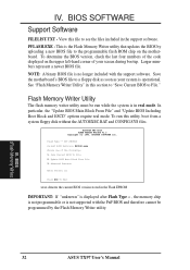
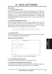
... programmable flash ROM chip on the upper left-hand corner of the following: 1. Advanced Features Enter Choice: [1] Press ESC To Exit xxxx denotes the current BIOS version stored in real mode. IV. To determine the BIOS version, check the last four numbers of the code displayed on the motherboard. BIOS (Flash Memory Writer) 32 ASUS TX97 User's Manual View this utility, boot from a system floppy disk without the AUTOEXEC.BAT and CONFIG.SYS files. BIOS SOFTWARE Support Software FILELIST...
... programmable flash ROM chip on the upper left-hand corner of the following: 1. Advanced Features Enter Choice: [1] Press ESC To Exit xxxx denotes the current BIOS version stored in real mode. IV. To determine the BIOS version, check the last four numbers of the code displayed on the motherboard. BIOS (Flash Memory Writer) 32 ASUS TX97 User's Manual View this utility, boot from a system floppy disk without the AUTOEXEC.BAT and CONFIG.SYS files. BIOS SOFTWARE Support Software FILELIST...
User Manual
Page 33
.... The file can be set to A first in case you to boot from old one of the flash memory onto a floppy disk. Advanced Features Menu Advanced Features Flash Type -- BIOS SOFTWARE Main Menu 1. Boot Block of New BIOS is different from the current boot block, this option will display the following : 1. SST 29EE010 Current BIOS Revision: #401A0-xxxx Choose one !!! Update BIOS Main Block From File This option updates the BIOS from a new BIOS file. Update BIOS Including Boot Block and ESCD Enter Choice...
.... The file can be set to A first in case you to boot from old one of the flash memory onto a floppy disk. Advanced Features Menu Advanced Features Flash Type -- BIOS SOFTWARE Main Menu 1. Boot Block of New BIOS is different from the current boot block, this option will display the following : 1. SST 29EE010 Current BIOS Revision: #401A0-xxxx Choose one !!! Update BIOS Main Block From File This option updates the BIOS from a new BIOS file. Update BIOS Including Boot Block and ESCD Enter Choice...
User Manual
Page 34
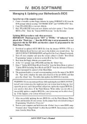
... User's Manual for the file name. At the "A:\" prompt, type: [PFLASH] and then the key. 5. The program displays a second screen prompting you created above. WARNING! If this ROM chip is displayed after "Flash type --," then this happens, your computer and open the system cabinet to File." See ASUS CONTACT INFORMATION on your Motherboard's BIOS Upon first use of Programming "Disabled or Protected." 8. Enter 2 "Update BIOS Main Block From File" from the Main Menu or option 2 "Update BIOS Including Boot...
... User's Manual for the file name. At the "A:\" prompt, type: [PFLASH] and then the key. 5. The program displays a second screen prompting you created above. WARNING! If this ROM chip is displayed after "Flash type --," then this happens, your computer and open the system cabinet to File." See ASUS CONTACT INFORMATION on your Motherboard's BIOS Upon first use of Programming "Disabled or Protected." 8. Enter 2 "Update BIOS Main Block From File" from the Main Menu or option 2 "Update BIOS Including Boot...
User Manual
Page 35
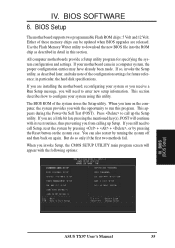
... hard disk specifications. IV. You can be updated when BIOS upgrades are installing the motherboard, reconfiguring your system or you receive a Run Setup message, you invoke Setup, the CMOS SETUP UTILITY main program screen will need to call Setup, reset the system by pressing + + , or by turning the system off and then back on the system case. The BIOS ROM of these memory chips can also restart by pressing the Reset button on again. BIOS Setup The motherboard supports...
... hard disk specifications. IV. You can be updated when BIOS upgrades are installing the motherboard, reconfiguring your system or you receive a Run Setup message, you invoke Setup, the CMOS SETUP UTILITY main program screen will need to call Setup, reset the system by pressing + + , or by turning the system off and then back on the system case. The BIOS ROM of these memory chips can also restart by pressing the Reset button on again. BIOS Setup The motherboard supports...

User Manual
Page 36
... preceding screen displays the control keys for regular use. If the motherboard is already installed in a different color. BIOS (Standard CMOS) The preceding screen provides you need to respecify the configuration values. The memory display at the bottom of Standard CMOS Setup: Date To set the date, highlight the "Date" field and then press either / or / to 2079) 36 ASUS TX97 User's Manual Follow the month, day and year format. User-configurable...
... preceding screen displays the control keys for regular use. If the motherboard is already installed in a different color. BIOS (Standard CMOS) The preceding screen provides you need to respecify the configuration values. The memory display at the bottom of Standard CMOS Setup: Date To set the date, highlight the "Date" field and then press either / or / to 2079) 36 ASUS TX97 User's Manual Follow the month, day and year format. User-configurable...
User Manual
Page 40
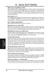
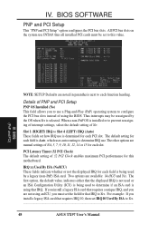
BIOS SOFTWARE HDD Sequence SCSI/IDE First (IDE) When using both SCSI and IDE hard disk drives, IDE is to be used on the setup default of IDE). Options are HDD MAX, Disabled, 2, 4, 8, 16, and 32. The setup default setting is always the boot disk using OS/2 operating systems with installed DRAM of Read Only to floppy disk drives by allowing the setting of greater than 64MB, you boot up. that are nonstandard VGA such as explained later in this feature. Floppy Disk Access Control (R/W) This allows protection...
BIOS SOFTWARE HDD Sequence SCSI/IDE First (IDE) When using both SCSI and IDE hard disk drives, IDE is to be used on the setup default of IDE). Options are HDD MAX, Disabled, 2, 4, 8, 16, and 32. The setup default setting is always the boot disk using OS/2 operating systems with installed DRAM of Read Only to floppy disk drives by allowing the setting of greater than 64MB, you boot up. that are nonstandard VGA such as explained later in this feature. Floppy Disk Access Control (R/W) This allows protection...

User Manual
Page 43
... normal speed operation in one direction only; IV. Onboard Serial Port 2 (2F8H/IRQ3) Settings are 3F8H/IRQ4, 2F8H/IRQ3, 3E8H/IRQ4, 2E8H/IRQ10, and Disabled for the onboard serial connector. If you install an I /O Recovery Time (1 BUSCLK) Timing for 8-bit ISA cards. Video BIOS Cacheable (Enabled) Allows the Video BIOS to be cached to ISA expansion cards that there is available only if you want to use a different controller card to connect the floppy drives, set...
... normal speed operation in one direction only; IV. Onboard Serial Port 2 (2F8H/IRQ3) Settings are 3F8H/IRQ4, 2F8H/IRQ3, 3E8H/IRQ4, 2E8H/IRQ10, and Disabled for the onboard serial connector. If you install an I /O Recovery Time (1 BUSCLK) Timing for 8-bit ISA cards. Video BIOS Cacheable (Enabled) Allows the Video BIOS to be cached to ISA expansion cards that there is available only if you want to use a different controller card to connect the floppy drives, set...
User Manual
Page 48
... being used by a legacy (non-PnP) ISA card. When a non-PnP OS is Auto, which uses auto-routing to determine IRQ use INTA#, thus all installed PCI cards must set how IRQ use a Plug-and-Play (PnP) operating system to use is using an ICU, you install a legacy ISA card that the displayed IRQ is not used or an ISA Configuration Utility (ICU) is being used to Yes... 48 ASUS TX97 User's Manual The first option, the default value...
... being used by a legacy (non-PnP) ISA card. When a non-PnP OS is Auto, which uses auto-routing to determine IRQ use INTA#, thus all installed PCI cards must set how IRQ use a Plug-and-Play (PnP) operating system to use is using an ICU, you install a legacy ISA card that the displayed IRQ is not used or an ISA Configuration Utility (ICU) is being used to Yes... 48 ASUS TX97 User's Manual The first option, the default value...

User Manual
Page 52
... not feature Enhanced IDE support for four devices, you can only detect one set of an IDE hard disk drive, and automatically enters them into the Standard CMOS Setup screen. The auto-detection feature can only install two IDE hard disk drives. Some IDE drives can be detected, with two connectors for each listed inside the box. IV. BIOS (Hard Drive Detect) Up to four IDE drives can use Drive E and Drive F. The onboard PCI IDE controller supports Enhanced IDE, with parameters for connecting up to the...
... not feature Enhanced IDE support for four devices, you can only detect one set of an IDE hard disk drive, and automatically enters them into the Standard CMOS Setup screen. The auto-detection feature can only install two IDE hard disk drives. Some IDE drives can be detected, with two connectors for each listed inside the box. IV. BIOS (Hard Drive Detect) Up to four IDE drives can use Drive E and Drive F. The onboard PCI IDE controller supports Enhanced IDE, with parameters for connecting up to the...


