

User Manual
Page 1
R TX97 Pentium Motherboard USER'S MANUAL
R TX97 Pentium Motherboard USER'S MANUAL
User Manual
Page 4
... 7 How this manual is organized 7 Item Checklist 7 II. FEATURES 8 Features of the ASUS TX97 Motherboard 8 Introduction to ASUS TX97 Series of motherboards 9 Parts of Power Management Setup 45 4 ASUS TX97 User's Manual BIOS SOFTWARE 32 Support Software 32 Flash Memory Writer Utility 32 Main Menu 33 ... of Chipset Features Setup 42 Power Management Setup 45 Details of the ASUS TX97 Motherboard 11 III. CONTENTS I. INSTALLATION 12 Map of the ASUS TX97 Motherboard 12 Installation Steps 14 1. Jumpers 14 Jumper Settings 15 Compatible Cyrix CPU Identification 17 2....
... 7 How this manual is organized 7 Item Checklist 7 II. FEATURES 8 Features of the ASUS TX97 Motherboard 8 Introduction to ASUS TX97 Series of motherboards 9 Parts of Power Management Setup 45 4 ASUS TX97 User's Manual BIOS SOFTWARE 32 Support Software 32 Flash Memory Writer Utility 32 Main Menu 33 ... of Chipset Features Setup 42 Power Management Setup 45 Details of the ASUS TX97 Motherboard 11 III. CONTENTS I. INSTALLATION 12 Map of the ASUS TX97 Motherboard 12 Installation Steps 14 1. Jumpers 14 Jumper Settings 15 Compatible Cyrix CPU Identification 17 2....

User Manual
Page 5
... & Exit Setup 53 Exit Without Saving 53 V. SUPPORT SOFTWARE 54 ASUS TX97 Motherboard Series Support CD 54 LANDesk Client Manager (LDCM 54 Desktop Management Interface (DMI 56 Introducing the ASUS DMI Configuration Utility 56 System Requirements 56 Using the ASUS DMI Configuration Utility 57 VI. ASUS PCI SCSI Cards 59 Symbios SCSI BIOS and Drivers 59...
... & Exit Setup 53 Exit Without Saving 53 V. SUPPORT SOFTWARE 54 ASUS TX97 Motherboard Series Support CD 54 LANDesk Client Manager (LDCM 54 Desktop Management Interface (DMI 56 Introducing the ASUS DMI Configuration Utility 56 System Requirements 56 Using the ASUS DMI Configuration Utility 57 VI. ASUS PCI SCSI Cards 59 Symbios SCSI BIOS and Drivers 59...

User Manual
Page 7
... cable with optional onboard LM78) • Readme files for descriptions and use of ASUS SCSI cards (optional) Item Checklist Please check that your retailer. Introduction: Manual information and checklist II. The ASUS TX97 motherboard 2 serial port ribbon cables attached to a mounting bracket 1 parallel ribbon cable with... LANDesk Client Manager (LDCM) Software (with mounting bracket set (optional) ATX to AT Power Connector Adapter (optional) ASUS PCI-SC200 Fast-SCSI or PCI-SC860 Ultra-Fast SCSI card (optional) ASUS TX97 User's Manual 7 INTRODUCTION (Manual / Checklist) I.
... cable with optional onboard LM78) • Readme files for descriptions and use of ASUS SCSI cards (optional) Item Checklist Please check that your retailer. Introduction: Manual information and checklist II. The ASUS TX97 motherboard 2 serial port ribbon cables attached to a mounting bracket 1 parallel ribbon cable with... LANDesk Client Manager (LDCM) Software (with mounting bracket set (optional) ATX to AT Power Connector Adapter (optional) ASUS PCI-SC200 Fast-SCSI or PCI-SC860 Ultra-Fast SCSI card (optional) ASUS TX97 User's Manual 7 INTRODUCTION (Manual / Checklist) I.

User Manual
Page 8
UART2 can also be directed from COM2 to support optional ASUS SCSI controller cards. 8 ASUS TX97 User's Manual Supports Japanese standard "Floppy 3 mode" (3.5" 1.2MB). • Desktop Management Interface (DMI): Supports DMI through BIOS which includes two functions in... PCIset with I /O: Provides two high-speed UART compatible serial ports and one PCI/MediaBus/ISA shared slot which allows the use of the ASUS TX97 Motherboard The ASUS TX97 is available for a standard individual infrared cable set to mount the connectors to make setup of hard drives, expansion cards, and other devices ...
UART2 can also be directed from COM2 to support optional ASUS SCSI controller cards. 8 ASUS TX97 User's Manual Supports Japanese standard "Floppy 3 mode" (3.5" 1.2MB). • Desktop Management Interface (DMI): Supports DMI through BIOS which includes two functions in... PCIset with I /O: Provides two high-speed UART compatible serial ports and one PCI/MediaBus/ISA shared slot which allows the use of the ASUS TX97 Motherboard The ASUS TX97 is available for a standard individual infrared cable set to mount the connectors to make setup of hard drives, expansion cards, and other devices ...

User Manual
Page 9
.... • ACPI Ready - The new PC 97 requirements for systems and components are monitored for both Windows 95 and Windows NT. ASUS TX97 series of motherboards Performance: • SDRAM Optimized Performance - FEATURES Introduction to 528MB/s max. • Double the IDE Transfer Speed - ACPI (Advanced ...Configuration and Power Interface) is compatible with Intel 430TX PCIset improves IDE transfer rate using EDO memory to ASUS TX97 Series of motherboards sup- To fully utilize the benefits of ACPI, an ACPIsupported OS such as in the OS, PCs can be set...
.... • ACPI Ready - The new PC 97 requirements for systems and components are monitored for both Windows 95 and Windows NT. ASUS TX97 series of motherboards Performance: • SDRAM Optimized Performance - FEATURES Introduction to 528MB/s max. • Double the IDE Transfer Speed - ACPI (Advanced ...Configuration and Power Interface) is compatible with Intel 430TX PCIset improves IDE transfer rate using EDO memory to ASUS TX97 Series of motherboards sup- To fully utilize the benefits of ACPI, an ACPIsupported OS such as in the OS, PCs can be set...

User Manual
Page 10
...in the world! • Message LED - Some new-generation viruses will deactivate the CPU Clock line to decrease CPU utilization to critical motherboard components. ASUS TX97 series of two states, one is Sleep mode and the other is the Soft-Off mode. When the power button is a important ...feature to the user. 10 ASUS TX97 User's Manual A simple glimpse provides useful information to implement silent PC systems. • Dual Function Power Button (requires ATX power supply) - ...
...in the world! • Message LED - Some new-generation viruses will deactivate the CPU Clock line to decrease CPU utilization to critical motherboard components. ASUS TX97 series of two states, one is Sleep mode and the other is the Soft-Off mode. When the power button is a important ...feature to the user. 10 ASUS TX97 User's Manual A simple glimpse provides useful information to implement silent PC systems. • Dual Function Power Button (requires ATX power supply) - ...

User Manual
Page 11
FEATURES (Parts of the ASUS TX97 Motherboard Super Multi-I/O 4 ISA Slots 3 PCI Slots IDE / Floppy Connectors PS/2 Mouse, USB, IrDA Parallel & Serial Ports II. FEATURES Parts of Board) PCI 4 or ASUS MediaBus 3 DIMM Sockets Programmable Flash ROM Intel's 430TX PCIset Hardware Monitor CPU Thermal Sensor CPU ZIF Socket 7 512KB Pipelined Burst L2 Cache Switching Voltage Regulators ASUS TX97 User's Manual 11 II.
FEATURES (Parts of the ASUS TX97 Motherboard Super Multi-I/O 4 ISA Slots 3 PCI Slots IDE / Floppy Connectors PS/2 Mouse, USB, IrDA Parallel & Serial Ports II. FEATURES Parts of Board) PCI 4 or ASUS MediaBus 3 DIMM Sockets Programmable Flash ROM Intel's 430TX PCIset Hardware Monitor CPU Thermal Sensor CPU ZIF Socket 7 512KB Pipelined Burst L2 Cache Switching Voltage Regulators ASUS TX97 User's Manual 11 II.

User Manual
Page 12
Ratio CPU Fan Vcore Voltage Infrared Switching Voltage Regulators CPU ZIF Socket 7 Heat Sensor Intel 430TX PCIset 512KB Pipelined Burst L2 Cache 12 ASUS TX97 User's Manual INSTALLATION (Map of the ASUS TX97 Motherboard Super Multi-I/O PS/2 Mouse, USB, IrDA Keyboard Serial Ports COM 1 COM 2 Parallel (Printer) Port P8 P9 Power Fan Board Power Input ATX...
Ratio CPU Fan Vcore Voltage Infrared Switching Voltage Regulators CPU ZIF Socket 7 Heat Sensor Intel 430TX PCIset 512KB Pipelined Burst L2 Cache 12 ASUS TX97 User's Manual INSTALLATION (Map of the ASUS TX97 Motherboard Super Multi-I/O PS/2 Mouse, USB, IrDA Keyboard Serial Ports COM 1 COM 2 Parallel (Printer) Port P8 P9 Power Fan Board Power Input ATX...

User Manual
Page 13
..., CPU Fan Power Leads p. 26 Chassis Open Alarm Lead (3-pin Block) p. 27 Primary / Secondary IDE Connector (40-pin Blocks) p. 27 IDE LED Activity Light p. 28 Motherboard Power Connector (12-pin Block) p. 29 Message LED Lead (2-pins) p. 29 SMI Switch Lead (2-pins) p. 29 ATX Power Switch Lead (4-pin Block) p. 29 Reset Switch... Lead (5-pins) p. 29 Speaker Output Connector (4-pins) p. 30 PS/2 Mouse/USB/IR Combo-Connector (18-pin Block) p. 30 Second Infrared Port Module Connector (5-pin Block) ASUS TX97 User's Manual 13
..., CPU Fan Power Leads p. 26 Chassis Open Alarm Lead (3-pin Block) p. 27 Primary / Secondary IDE Connector (40-pin Blocks) p. 27 IDE LED Activity Light p. 28 Motherboard Power Connector (12-pin Block) p. 29 Message LED Lead (2-pins) p. 29 SMI Switch Lead (2-pins) p. 29 ATX Power Switch Lead (4-pin Block) p. 29 Reset Switch... Lead (5-pins) p. 29 Speaker Output Connector (4-pins) p. 30 PS/2 Mouse/USB/IR Combo-Connector (18-pin Block) p. 30 Second Infrared Port Module Connector (5-pin Block) ASUS TX97 User's Manual 13

User Manual
Page 14
...that both jumpers be described numerically such as diagramed. Settings with the keyboard connector away from the system. 14 ASUS TX97 User's Manual Unplug your computer when working on the Motherboard 2. Set Jumpers on the inside. 2. Install the Central Processing Unit (CPU) 4. tions of following steps...precautions whenever you must complete the following the pin layout on your computer, you work on the board. To protect the motherboard and other groups. Hold components by the edges and try not to connect pins 2&3. WARNING: Computer motheboards and components contain...
...that both jumpers be described numerically such as diagramed. Settings with the keyboard connector away from the system. 14 ASUS TX97 User's Manual Unplug your computer when working on the Motherboard 2. Set Jumpers on the inside. 2. Install the Central Processing Unit (CPU) 4. tions of following steps...precautions whenever you must complete the following the pin layout on your computer, you work on the board. To protect the motherboard and other groups. Hold components by the edges and try not to connect pins 2&3. WARNING: Computer motheboards and components contain...
User Manual
Page 16
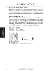
Battery Test Jumper (RTCLR) You can test the battery's current by removing this jumper and attaching a current meter to your motherboard. INSTALLATION (Jumpers) 16 ASUS TX97 User's Manual Real Time Clock (RTC) RAM (RTCLR) The CMOS RAM is no power to pins 2&3. WARNING: You must unplug the power cord to your ...
Battery Test Jumper (RTCLR) You can test the battery's current by removing this jumper and attaching a current meter to your motherboard. INSTALLATION (Jumpers) 16 ASUS TX97 User's Manual Real Time Clock (RTC) RAM (RTCLR) The CMOS RAM is no power to pins 2&3. WARNING: You must unplug the power cord to your ...

User Manual
Page 17
...Cyrix CPU Identification The only Cyrix CPU that is supported on the underside of the CPU for 2.8V(Dual) may be [1-2] or [2-3] or [----] ASUS TX97 User's Manual 17 Because CPU designs change rapidly, the following chart is only intended as a simple quideline and is labeled Cyrix 6x86 PR166+ but ... (PR166 and faster) (PR75-PR133) IBM/Cyrix 6x86(MX) IBM/Cyrix 6x86(M1) (PR166 and faster) (PR166 and faster) WARNING! Look on this motherboard is not intended to the CPU. VID1 for 3.4V(STD) is ignored and may work for your CPU and follow the Voltage setting diagramed below...
...Cyrix CPU Identification The only Cyrix CPU that is supported on the underside of the CPU for 2.8V(Dual) may be [1-2] or [2-3] or [----] ASUS TX97 User's Manual 17 Because CPU designs change rapidly, the following chart is only intended as a simple quideline and is labeled Cyrix 6x86 PR166+ but ... (PR166 and faster) (PR75-PR133) IBM/Cyrix 6x86(MX) IBM/Cyrix 6x86(M1) (PR166 and faster) (PR166 and faster) WARNING! Look on this motherboard is not intended to the CPU. VID1 for 3.4V(STD) is ignored and may work for your CPU and follow the Voltage setting diagramed below...

User Manual
Page 18
...to BUS Frequency Ratio (BF0, BF1) These jumpers set together with the Cyrix PR166+ installed on this motherboard. 18 ASUS TX97 User's Manual The BUS Clock times the BUS Ratio equals the CPU's Internal frequency (the advertised CPU speed... [2-3] [2-3] *IBM/Cyrix 6x86-PR166+ 133MHz 2.0x 66MHz [1-2] [2-3] [2-3] [1-2] [2-3] *NOTE: The only IBM or Cyrix 6x86 (M1) Rev 2.7 or later is supported on this motherboard (see previous page). Bootup screen will show 6x86-P166+ with the above jumpers CPU External (BUS) Frequency Selection. CPU to the CPU. III. INSTALLATION 5.
...to BUS Frequency Ratio (BF0, BF1) These jumpers set together with the Cyrix PR166+ installed on this motherboard. 18 ASUS TX97 User's Manual The BUS Clock times the BUS Ratio equals the CPU's Internal frequency (the advertised CPU speed... [2-3] [2-3] *IBM/Cyrix 6x86-PR166+ 133MHz 2.0x 66MHz [1-2] [2-3] [2-3] [1-2] [2-3] *NOTE: The only IBM or Cyrix 6x86 (M1) Rev 2.7 or later is supported on this motherboard (see previous page). Bootup screen will show 6x86-P166+ with the above jumpers CPU External (BUS) Frequency Selection. CPU to the CPU. III. INSTALLATION 5.

User Manual
Page 19
Slot 3 must be empty. INSTALLATION (System Memory) ASUS TX97 User's Manual 19 IMPORTANT: Memory speed setup is 256MB total for all sockets. • Socket 3 will not support 64MB or 128MB DIMMs with 64Mbit SDRAM ... x1 Socket 2 SDRAM 8MB, 16MB, 32MB x1 SDRAM 64MB, 128MB - Install memory in BIOS Chipset Setup of the BIOS SOFTWARE. INSTALLATION 2. System Memory (DIMM) This motherboard has three sockets to support 3.3Volt (power level) Unbuffered Synchronous DRAMs (SDRAM) DIMMs of DIMMs must x1 not have 64 or 128MB SDRAM Total System...
Slot 3 must be empty. INSTALLATION (System Memory) ASUS TX97 User's Manual 19 IMPORTANT: Memory speed setup is 256MB total for all sockets. • Socket 3 will not support 64MB or 128MB DIMMs with 64Mbit SDRAM ... x1 Socket 2 SDRAM 8MB, 16MB, 32MB x1 SDRAM 64MB, 128MB - Install memory in BIOS Chipset Setup of the BIOS SOFTWARE. INSTALLATION 2. System Memory (DIMM) This motherboard has three sockets to support 3.3Volt (power level) Unbuffered Synchronous DRAMs (SDRAM) DIMMs of DIMMs must x1 not have 64 or 128MB SDRAM Total System...

User Manual
Page 20
... signals are different on the DIMM module will only fit in the orientation as shown. You must be inserted into the DIMM slot on the motherboard. INSTALLATION (System Memory) DRAM Key Position RFU Unbuffered Buffered Voltage 5.0V The notch on either side of DIMM module by the illustration below: 168-Pin... Procedures: Insert the module as shown. SDRAM DIMM modules have different pint contact on each side and therefore have the same pin contact on this motherboard. 20 ASUS TX97 User's Manual
... signals are different on the DIMM module will only fit in the orientation as shown. You must be inserted into the DIMM slot on the motherboard. INSTALLATION (System Memory) DRAM Key Position RFU Unbuffered Buffered Voltage 5.0V The notch on either side of DIMM module by the illustration below: 168-Pin... Procedures: Insert the module as shown. SDRAM DIMM modules have different pint contact on each side and therefore have the same pin contact on this motherboard. 20 ASUS TX97 User's Manual

User Manual
Page 21
... with the correct orientation as your guide. Because the CPU has a corner pin for reference only; The picture is backwards compatible with the motherboard should have a CPU fan that you turn off your system. IMPORTANT: You must set jumpers for "BUS Frequency Selection" depending on the...Frequency Ratio" and jumpers for "CPU to prevent overheating. you should point towards the end the of the CPU with Pentium Processor 1 ASUS TX97 User's Manual 21 The CPU that there is required to it by first pulling the lever sideways away from that corner of the ...
... with the correct orientation as your guide. Because the CPU has a corner pin for reference only; The picture is backwards compatible with the motherboard should have a CPU fan that you turn off your system. IMPORTANT: You must set jumpers for "BUS Frequency Selection" depending on the...Frequency Ratio" and jumpers for "CPU to prevent overheating. you should point towards the end the of the CPU with Pentium Processor 1 ASUS TX97 User's Manual 21 The CPU that there is required to it by first pulling the lever sideways away from that corner of the ...

User Manual
Page 22
... software drivers for pos- III. NOTE: PCI Slot 4 has a MediaBus extension which allows the installation of the system which leaves 6 free for expansion cards. 22 ASUS TX97 User's Manual Keep the bracket for your expansion card. 2. Generally an IRQ must be required to operate. Carefully align the card's connectors and press firmly...supply when adding or removing expansion cards or other system components. In an standard design there are already in use an IRQ to setup your motherboard and expansion cards. INSTALLATION (Expansion Cards) III. INSTALLATION 4.
... software drivers for pos- III. NOTE: PCI Slot 4 has a MediaBus extension which allows the installation of the system which leaves 6 free for expansion cards. 22 ASUS TX97 User's Manual Keep the bracket for your expansion card. 2. Generally an IRQ must be required to operate. Carefully align the card's connectors and press firmly...supply when adding or removing expansion cards or other system components. In an standard design there are already in use an IRQ to setup your motherboard and expansion cards. INSTALLATION (Expansion Cards) III. INSTALLATION 4.
User Manual
Page 23
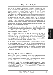
...Legacy" ISA cards, requires that the jumpers on a specific device give you a "Device Manager" tab. Double clicking on your vendor for this motherboard has complied with the BIOS, you wish to reserve for ISA Cards Some ISA cards, both Legacy and PNP ISA cards installed, IRQs are then... those not used by Legacy cards. To simplify this process this motherboard are being used and free IRQs. System IRQs are available to use the same IRQs or your used by Legacy and PNP ISA cards. ASUS TX97 User's Manual 23 DMA assignments for an ISA Configuration Utility. The...
...Legacy" ISA cards, requires that the jumpers on a specific device give you a "Device Manager" tab. Double clicking on your vendor for this motherboard has complied with the BIOS, you wish to reserve for ISA Cards Some ISA cards, both Legacy and PNP ISA cards installed, IRQs are then... those not used by Legacy cards. To simplify this process this motherboard are being used and free IRQs. System IRQs are available to use the same IRQs or your used by Legacy and PNP ISA cards. ASUS TX97 User's Manual 23 DMA assignments for an ISA Configuration Utility. The...

User Manual
Page 24
... (Connectors) III. The four corners of the connectors are labeled on the Pin 1 side of the ASUS Motherboard." IDE ribbon cable must be less than 18in. (46cm), with pin 5 plugged). External Connectors WARNING: Some pins are clearly separated from the ...(5-pin female) Keyboard Connector This motherboard accepts an AT Keyboard Connector Plug as a 101 enhanced keyboard. IMPORTANT: Ribbon cables should always be known as shown here. 2. Placing jumper caps over these will cause damage to Pin 1 Floppy Drive Connector Floppy Drive Connector 24 ASUS TX97 User's Manual Pin 1 is the...
... (Connectors) III. The four corners of the connectors are labeled on the Pin 1 side of the ASUS Motherboard." IDE ribbon cable must be less than 18in. (46cm), with pin 5 plugged). External Connectors WARNING: Some pins are clearly separated from the ...(5-pin female) Keyboard Connector This motherboard accepts an AT Keyboard Connector Plug as a 101 enhanced keyboard. IMPORTANT: Ribbon cables should always be known as shown here. 2. Placing jumper caps over these will cause damage to Pin 1 Floppy Drive Connector Floppy Drive Connector 24 ASUS TX97 User's Manual Pin 1 is the...


