User Guide
Page 8
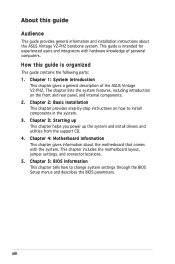
...settings through the BIOS Setup menus and describes the BIOS parameters. Chapter 4: Motherboard information This chapter gives information about the ASUS Vintage V2-PH2 barebone system. Chapter 5: BIOS information This chapter tells how to install components in the system. 3. Chapter 1: System ... guide Audience This guide provides general information and installation instructions about the motherboard that comes with hardware knowledge of the ASUS Vintage V2-PH2. Chapter 3: Starting up This chapter helps you power up the system and install drivers and utilities from the support...
...settings through the BIOS Setup menus and describes the BIOS parameters. Chapter 4: Motherboard information This chapter gives information about the ASUS Vintage V2-PH2 barebone system. Chapter 5: BIOS information This chapter tells how to install components in the system. 3. Chapter 1: System ... guide Audience This guide provides general information and installation instructions about the motherboard that comes with hardware knowledge of the ASUS Vintage V2-PH2. Chapter 3: Starting up This chapter helps you power up the system and install drivers and utilities from the support...

User Guide
Page 10
Support CD 4. User guide x Cable • AC power cable 3. Item description 1. System package contents Check your Vintage V2-PH2 system package for the following items. If any of the items is damaged or missing, contact your retailer immediately. ASUS Vintage V2-PH2 barebone system with • ASUS motherboard • 300 W PFC power supply unit • ASUS chassis 2.
Support CD 4. User guide x Cable • AC power cable 3. Item description 1. System package contents Check your Vintage V2-PH2 system package for the following items. If any of the items is damaged or missing, contact your retailer immediately. ASUS Vintage V2-PH2 barebone system with • ASUS motherboard • 300 W PFC power supply unit • ASUS chassis 2.
User Guide
Page 11
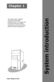
System introduction Chapter 1 This chapter gives a general description of the ASUS Vintage V2-PH2. The chapter lists the system features including introduction on the front and rear panel, and internal components. ASUS Vintage V2-PH2
System introduction Chapter 1 This chapter gives a general description of the ASUS Vintage V2-PH2. The chapter lists the system features including introduction on the front and rear panel, and internal components. ASUS Vintage V2-PH2

User Guide
Page 12
1.1 Welcome! The system comes in a stylish mini-tower casing and powered by the ASUS motherboard that supports the Intel® Pentium® D, Intel® Pentium® 4 or Intel® Celeron® processor in the world of power computing. 1.2 Front ... of system memory using DDR2-667/533 DIMMs, ATI integrated graphics, Serial ATA, USB 2.0, and 6-channel audio features the system takes you for choosing the ASUS Vintage V2-PH2! The ASUS Vintage V2-PH2 is an all-in-one barebone system with a versatile home entertainment feature.
1.1 Welcome! The system comes in a stylish mini-tower casing and powered by the ASUS motherboard that supports the Intel® Pentium® D, Intel® Pentium® 4 or Intel® Celeron® processor in the world of power computing. 1.2 Front ... of system memory using DDR2-667/533 DIMMs, ATI integrated graphics, Serial ATA, USB 2.0, and 6-channel audio features the system takes you for choosing the ASUS Vintage V2-PH2! The ASUS Vintage V2-PH2 is an all-in-one barebone system with a versatile home entertainment feature.
User Guide
Page 13
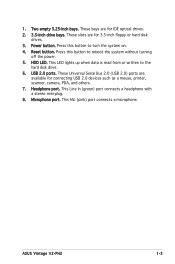
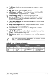
... floppy or hard disk drives. 3. This Mic (pink) port connects a microphone. This Line In (green) port connects a headphone with a stereo mini-plug. 8. Headphone port. ASUS Vintage V2-PH2 1-3 Two empty 5.25-inch bays. Press this button to the hard disk drive. 6.
... floppy or hard disk drives. 3. This Mic (pink) port connects a microphone. This Line In (green) port connects a headphone with a stereo mini-plug. 8. Headphone port. ASUS Vintage V2-PH2 1-3 Two empty 5.25-inch bays. Press this button to the hard disk drive. 6.
User Guide
Page 15
... Blue Lime Pink Headset 2-s p e a k e r Line In Line Out Mic In 4-speaker Surround Out Front Speaker Out Mic 6-speaker Surround Out Front Speaker Out Center/Bass ASUS Vintage V2-PH2 1-5 This port connects a VGA monitor. 8. This port connects a microphone. 10. Power supply unit fan vent. These 4-pin Universal Serial Bus (USB) ports are available for...
... Blue Lime Pink Headset 2-s p e a k e r Line In Line Out Mic In 4-speaker Surround Out Front Speaker Out Mic 6-speaker Surround Out Front Speaker Out Center/Bass ASUS Vintage V2-PH2 1-5 This port connects a VGA monitor. 8. This port connects a microphone. 10. Power supply unit fan vent. These 4-pin Universal Serial Bus (USB) ports are available for...
User Guide
Page 17
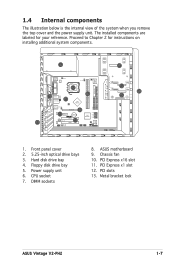
... your reference. Power supply unit 6. DIMM sockets 8. PCI Express x1 slot 12. Floppy disk drive bay 5. CPU socket 7. Metal bracket lock ASUS Vintage V2-PH2 1-7 Front panel cover 2. 5.25-inch optical drive bays 3. ASUS motherboard 9. 1.4 Internal components The illustration below is the internal view of the system when you remove the top cover and the...
... your reference. Power supply unit 6. DIMM sockets 8. PCI Express x1 slot 12. Floppy disk drive bay 5. CPU socket 7. Metal bracket lock ASUS Vintage V2-PH2 1-7 Front panel cover 2. 5.25-inch optical drive bays 3. ASUS motherboard 9. 1.4 Internal components The illustration below is the internal view of the system when you remove the top cover and the...

User Guide
Page 21
Remove the front panel assembly, then set aside. Set the side cover aside. 3. Locate the front panel assembly hooks, then lift them until they disengage from the chassis tab holes. Remove the cover screws on the right side of the assembly are exposed. 5. Air duct 3 1 2 3 1 3 2 Chassis tab holes 4 4 4 4 ASUS Vintage V2-PH2 2-3 Pull the side cover toward the rear panel until the hinge-like tabs on the rear panel. 2. Swing the front panel assembly to the right, until its hooks disengage from the chassis. 4. 2.3 Removing the side cover and front panel assembly 1.
Remove the front panel assembly, then set aside. Set the side cover aside. 3. Locate the front panel assembly hooks, then lift them until they disengage from the chassis tab holes. Remove the cover screws on the right side of the assembly are exposed. 5. Air duct 3 1 2 3 1 3 2 Chassis tab holes 4 4 4 4 ASUS Vintage V2-PH2 2-3 Pull the side cover toward the rear panel until the hinge-like tabs on the rear panel. 2. Swing the front panel assembly to the right, until its hooks disengage from the chassis. 4. 2.3 Removing the side cover and front panel assembly 1.
User Guide
Page 23
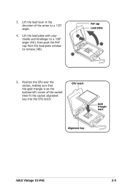
CPU notch Gold triangle mark Alignment key ASUS Vintage V2-PH2 2-5 Lift the load plate with your thumb and forefinger to a 100º angle (4A), then push the PnP cap from the load plate window to a 135º angle. 4. Position the CPU over the socket, making sure that the gold triangle is on the bottom-left corner of the arrow to remove (4B). 4B 3 PnP cap Load plate 4A 5. 3. Lift the load lever in the direction of the socket then fit the socket alignment key into the CPU notch.
CPU notch Gold triangle mark Alignment key ASUS Vintage V2-PH2 2-5 Lift the load plate with your thumb and forefinger to a 100º angle (4A), then push the PnP cap from the load plate window to a 135º angle. 4. Position the CPU over the socket, making sure that the gold triangle is on the bottom-left corner of the arrow to remove (4B). 4B 3 PnP cap Load plate 4A 5. 3. Lift the load lever in the direction of the socket then fit the socket alignment key into the CPU notch.
User Guide
Page 25
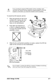
... can occur if you install the heatsink and fan assembly. Push down two fasteners at a time in a diagonal sequence to connect the CPU fan connector! ASUS Vintage V2-PH2 2-7 If you purchased a separate CPU heatsink and fan assembly, make sure that B the four fasteners match the holes on the motherboard. Place the heatsink on...
... can occur if you install the heatsink and fan assembly. Push down two fasteners at a time in a diagonal sequence to connect the CPU fan connector! ASUS Vintage V2-PH2 2-7 If you purchased a separate CPU heatsink and fan assembly, make sure that B the four fasteners match the holes on the motherboard. Place the heatsink on...
User Guide
Page 27
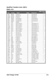
...-A8EB4 V V TS64MLQ64V5J V TS128MLQ64V5J V V 25V6S8SSD5F4-K43 V V 25V0H8EL5CB4-J45 V V M2U51264TU88A0F-37B V AET560UD00-370A98X V AET560UD00-370A98X V V AET660UD00-370A98Z V V AET760UD00-370A98X V V NT512T64U88A0F-37B V V MEAB-423LA V PDC21G5600+XBLK V M512-533-8 V ASUS Vintage V2-PH2 2-9
...-A8EB4 V V TS64MLQ64V5J V TS128MLQ64V5J V V 25V6S8SSD5F4-K43 V V 25V0H8EL5CB4-J45 V V M2U51264TU88A0F-37B V AET560UD00-370A98X V AET560UD00-370A98X V V AET660UD00-370A98Z V V AET760UD00-370A98X V V NT512T64U88A0F-37B V V MEAB-423LA V PDC21G5600+XBLK V M512-533-8 V ASUS Vintage V2-PH2 2-9

User Guide
Page 29
... back in only one direction. Locked Retaining Clip 2.5.3 Removing a DDR2 DIMM Follow these steps to avoid damaging the DIMM. 3. Remove the DIMM from the socket. ASUS Vintage V2-PH2 2-11 Simultaneously press the retaining clips outward to unlock the DIMM. 1 1 DDR2 DIMM notch Support the DIMM lightly with a notch so that the notch on...
... back in only one direction. Locked Retaining Clip 2.5.3 Removing a DDR2 DIMM Follow these steps to avoid damaging the DIMM. 3. Remove the DIMM from the socket. ASUS Vintage V2-PH2 2-11 Simultaneously press the retaining clips outward to unlock the DIMM. 1 1 DDR2 DIMM notch Support the DIMM lightly with a notch so that the notch on...
User Guide
Page 31
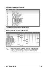
shared - - - shared - - - shared - - - - Otherwise, conflicts will arise between the two PCI groups, making the system unstable and the card inoperable. ASUS Vintage V2-PH2 2-13 shared - - - - - - shared - - - - - - shared - - - - - - - - IRQ assignments for ISA or PCI devices. shared - - - - - - - - shared - - - - - - - - - - - - - Standard interrupt assignments IRQ Standard Function 0 System Timer 1 Keyboard Controller 2 Re-direct ...
shared - - - shared - - - shared - - - - Otherwise, conflicts will arise between the two PCI groups, making the system unstable and the card inoperable. ASUS Vintage V2-PH2 2-13 shared - - - - - - shared - - - - - - shared - - - - - - - - IRQ assignments for ISA or PCI devices. shared - - - - - - - - shared - - - - - - - - - - - - - Standard interrupt assignments IRQ Standard Function 0 System Timer 1 Keyboard Controller 2 Re-direct ...

User Guide
Page 33
... power supply to the IDE interface at the back of the bay. 3 4 4 5. Follow these steps to install a new optical drive. IDE ribbon cable Power cable ASUS Vintage V2-PH2 2-15 2.7 Installing an optical drive Refer to the instructions in this section if you wish to install an optical drive: 1. Insert the optical drive into...
... power supply to the IDE interface at the back of the bay. 3 4 4 5. Follow these steps to install a new optical drive. IDE ribbon cable Power cable ASUS Vintage V2-PH2 2-15 2.7 Installing an optical drive Refer to the instructions in this section if you wish to install an optical drive: 1. Insert the optical drive into...
User Guide
Page 35
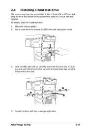
... hard disk drive(s). Secure the drive with the holes on both sides. Refer to this section to remove the HDD drive slot metal plate cover. 3. ASUS Vintage V2-PH2 2-17 To install a Serial ATA hard disk drive: 1. With the HDD label side up, carefully insert the drive into the 3.5-inch bay and push the...
... hard disk drive(s). Secure the drive with the holes on both sides. Refer to this section to remove the HDD drive slot metal plate cover. 3. ASUS Vintage V2-PH2 2-17 To install a Serial ATA hard disk drive: 1. With the HDD label side up, carefully insert the drive into the 3.5-inch bay and push the...
User Guide
Page 37
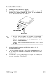
... the IDE connector on the motherboard. Connect a 4-pin power plug from the power supply unit to configure your hard disk drive as Slave. 3. ASUS Vintage V2-PH2 2-19 Follow steps 1-4 of the connector. To install an IDE hard disk drive: 1.
... the IDE connector on the motherboard. Connect a 4-pin power plug from the power supply unit to configure your hard disk drive as Slave. 3. ASUS Vintage V2-PH2 2-19 Follow steps 1-4 of the connector. To install an IDE hard disk drive: 1.
User Guide
Page 38
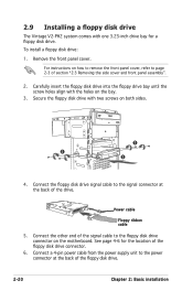
... at the back of section "2.3 Removing the side cover and front panel assembly". 2. To install a floppy disk drive: 1. 2.9 Installing a floppy disk drive The Vintage V2-PH2 system comes with the holes on both sides. 3 3 2 4. Secure the floppy disk drive with two screws on the bay. 3. Power cable Floppy ribbon cable...
... at the back of section "2.3 Removing the side cover and front panel assembly". 2. To install a floppy disk drive: 1. 2.9 Installing a floppy disk drive The Vintage V2-PH2 system comes with the holes on both sides. 3 3 2 4. Secure the floppy disk drive with two screws on the bay. 3. Power cable Floppy ribbon cable...

User Guide
Page 39
... Reset Ground ® System Panel Connector IDE_LED RESET PWRSW * Requires an ATX power supply. You must re-connect these cables before you were installing components. ASUS Vintage V2-PH2 2-21 Connect the reset button, power switch, power LED, and HDD LED cables to their respective leads in the system panel connector on the motherboard...
... Reset Ground ® System Panel Connector IDE_LED RESET PWRSW * Requires an ATX power supply. You must re-connect these cables before you were installing components. ASUS Vintage V2-PH2 2-21 Connect the reset button, power switch, power LED, and HDD LED cables to their respective leads in the system panel connector on the motherboard...
User Guide
Page 41
ASUS Vintage V2-PH2 Starting up the system and install drivers and utilities from the support CD. Chapter 3 This chapter helps you power up
ASUS Vintage V2-PH2 Starting up the system and install drivers and utilities from the support CD. Chapter 3 This chapter helps you power up
User Guide
Page 43
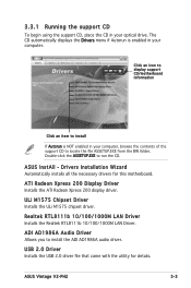
.../100/1000M LAN Driver. USB 2.0 Driver Installs the USB 2.0 driver file that came with the utility for this motherboard. ASUS Vintage V2-PH2 3-3 The CD automatically displays the Drivers menu if Autorun is NOT enabled in your optical drive. ASUS InstAll - ADI AD1986A Audio Driver Allows you to install the ADI AD1986A audio driver.
.../100/1000M LAN Driver. USB 2.0 Driver Installs the USB 2.0 driver file that came with the utility for this motherboard. ASUS Vintage V2-PH2 3-3 The CD automatically displays the Drivers menu if Autorun is NOT enabled in your optical drive. ASUS InstAll - ADI AD1986A Audio Driver Allows you to install the ADI AD1986A audio driver.