
User Guide
Page 3
Contents Safety information...v About this guide...vi X99-A/USB 3.1 specifications summary viii Package contents...xiv Installation tools and components xv Chapter 1: Product Introduction 1.1 Special ...and fan assembly installation 2-4 2.1.4 DIMM installation 2-6 2.1.5 ATX Power connection 2-7 2.1.6 SATA device connection 2-8 2.1.7 Front I/O Connector 2-9 2.1.8 Expansion Card installation 2-10 2.2 BIOS update utility 2-11 2.3 Motherboard rear and audio connections 2-12 2.3.1 Rear I/O connection 2-12 2.3.2 Audio I/O connections 2-14 2.4 Starting up for the first time 2-...
Contents Safety information...v About this guide...vi X99-A/USB 3.1 specifications summary viii Package contents...xiv Installation tools and components xv Chapter 1: Product Introduction 1.1 Special ...and fan assembly installation 2-4 2.1.4 DIMM installation 2-6 2.1.5 ATX Power connection 2-7 2.1.6 SATA device connection 2-8 2.1.7 Front I/O Connector 2-9 2.1.8 Expansion Card installation 2-10 2.2 BIOS update utility 2-11 2.3 Motherboard rear and audio connections 2-12 2.3.1 Rear I/O connection 2-12 2.3.2 Audio I/O connections 2-14 2.4 Starting up for the first time 2-...
User Guide
Page 4
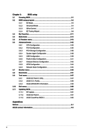
... 3.11.3 ASUS CrashFree BIOS 3 3-63 Appendices Notices ...A-1 ASUS contact information A-5 iv Chapter 3: BIOS setup 3.1 Knowing BIOS 3-1 3.2 BIOS setup program 3-2 3.2.1 EZ Mode 3-3 3.2.2 Advanced Mode 3-4 3.2.3 QFan Control 3-7 3.2.4 EZ Tuning Wizard 3-9 3.3 My Favorites 3-11 3.4 Main menu 3-13 3.5 Ai Tweaker menu 3-15 3.6 Advanced menu 3-32 3.6.1 CPU Configuration 3-33 3.6.2 PCH Configuration 3-35 3.6.3 PCH Storage Configuration 3-36 3.6.4 System Agent Configuration 3-38 3.6.5 USB Configuration...
... 3.11.3 ASUS CrashFree BIOS 3 3-63 Appendices Notices ...A-1 ASUS contact information A-5 iv Chapter 3: BIOS setup 3.1 Knowing BIOS 3-1 3.2 BIOS setup program 3-2 3.2.1 EZ Mode 3-3 3.2.2 Advanced Mode 3-4 3.2.3 QFan Control 3-7 3.2.4 EZ Tuning Wizard 3-9 3.3 My Favorites 3-11 3.4 Main menu 3-13 3.5 Ai Tweaker menu 3-15 3.6 Advanced menu 3-32 3.6.1 CPU Configuration 3-33 3.6.2 PCH Configuration 3-35 3.6.3 PCH Storage Configuration 3-36 3.6.4 System Agent Configuration 3-38 3.6.5 USB Configuration...
User Guide
Page 6
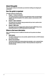
... the standard package. Where to find more information Refer to change system settings through the BIOS Setup menus. ASUS website The ASUS website (www.asus.com) provides updated information on the motherboard. 2. These documents are not part of the BIOS parameters are also provided. About this guide is organized This guide contains the following sources...
... the standard package. Where to find more information Refer to change system settings through the BIOS Setup menus. ASUS website The ASUS website (www.asus.com) provides updated information on the motherboard. 2. These documents are not part of the BIOS parameters are also provided. About this guide is organized This guide contains the following sources...

User Guide
Page 10
... Remote GO! Whole system optimization with ThunderboltEX II series Powerful Home Server ASUS HomeCloud Server Remote GO! - ASUS DRAM power utility TPU - Design - capability under full load by Dual Intelligent Processors 5 - EPU, EPU switch ASUS Fan Xpert3 - X99-A/USB 3.1 specifications summary ASUS Exclusive Features Flagship Performance 5-Way Optimization by minimizing the coupling noise and ... data transfer speeds for SATA Express Special Memory O.C. Industry leading digital 4-phase DRAM power design - Superb memory O.C. DIGI+ Power Control CPU Power - UEFI BIOS -
... Remote GO! Whole system optimization with ThunderboltEX II series Powerful Home Server ASUS HomeCloud Server Remote GO! - ASUS DRAM power utility TPU - Design - capability under full load by Dual Intelligent Processors 5 - EPU, EPU switch ASUS Fan Xpert3 - X99-A/USB 3.1 specifications summary ASUS Exclusive Features Flagship Performance 5-Way Optimization by minimizing the coupling noise and ... data transfer speeds for SATA Express Special Memory O.C. Industry leading digital 4-phase DRAM power design - Superb memory O.C. DIGI+ Power Control CPU Power - UEFI BIOS -

User Guide
Page 11
... Crystal Sound 2 - ASUS CrashFree BIOS 3 - ASUS EZ Flash 2 Q-Design - ASUS Q-DIMM - NFC Receiver and 2-port USB 3.0 hub - with tailored performance, network priority, audio configuration, and fan speed for EZ BIOS download scheduling UEFI BIOS EZ Mode - ASUS Q-LED (CPU, DRAM, VGA, Boot Device LED) - ASUS O.C. ASUS Q-Code - ASUS Q-Shield - ASUS Q-Connector (continued on the next page) xi X99-A/USB 3.1 specifications summary ASUS Exclusive Features - Tuner...
... Crystal Sound 2 - ASUS CrashFree BIOS 3 - ASUS EZ Flash 2 Q-Design - ASUS Q-DIMM - NFC Receiver and 2-port USB 3.0 hub - with tailored performance, network priority, audio configuration, and fan speed for EZ BIOS download scheduling UEFI BIOS EZ Mode - ASUS Q-LED (CPU, DRAM, VGA, Boot Device LED) - ASUS O.C. ASUS Q-Code - ASUS Q-Shield - ASUS Q-Connector (continued on the next page) xi X99-A/USB 3.1 specifications summary ASUS Exclusive Features - Tuner...

User Guide
Page 12
... SFS (Stepless Frequency Selection) - X99-A/USB 3.1 specifications summary ASUS Special Features ASUS Quiet Thermal Solution ASUS Exclusive Overclocking Features Rear Panel I/O Ports Internal I /O - 3x more durable corrosionresistant coating USB 3.1 Boost USB Charger+ Ai Charger+ Disk Unlocker ...110-step Memory voltage control - ASUS C.P.R. (CPU Parameter Recall) 1 x BIOS Flashback button 1 x Optical S/PDIF Out port 1 x Intel® LAN (RJ45) port 2 x USB 3.1/3.0/2.0 ports (teal blue) 4 x USB 3.0/2.0 ports (blue) 4 x USB 2.0/1.1 ports (bottom port supports USB BIOS Flashback) 1 x Keyboard/Mouse...
... SFS (Stepless Frequency Selection) - X99-A/USB 3.1 specifications summary ASUS Special Features ASUS Quiet Thermal Solution ASUS Exclusive Overclocking Features Rear Panel I/O Ports Internal I /O - 3x more durable corrosionresistant coating USB 3.1 Boost USB Charger+ Ai Charger+ Disk Unlocker ...110-step Memory voltage control - ASUS C.P.R. (CPU Parameter Recall) 1 x BIOS Flashback button 1 x Optical S/PDIF Out port 1 x Intel® LAN (RJ45) port 2 x USB 3.1/3.0/2.0 ports (teal blue) 4 x USB 3.0/2.0 ports (blue) 4 x USB 2.0/1.1 ports (bottom port supports USB BIOS Flashback) 1 x Keyboard/Mouse...

User Guide
Page 13
X99-A/USB 3.1 specifications summary Internal I/O Connectors BIOS features Manageability Support DVD Operating system Form Factors 1 x SATA Express connectors (gray) 8 x SATA 6.0 Gb/s connectors (4 x gray, 4 x black) 1 x 4-pin CPU Fan connector for both... adjustments) 1 x EPU switch 1 x EZ XMP switch 1 x Power-on button 1 x Reset button 128 Mb Flash ROM, UEFI AMI BIOS, PnP, DMI 2.7, WfM 2.0, SM BIOS 2.7, ACPI 5.0, Multi-language BIOS, ASUS EZ Flash 2, CrashFree BIOS 3, F11 EZ Tuning Wizard, F6 Qfan Control, F3 My Favorites, Quick Note, Last Modified Log, F12 PrintScreen function, F3 Shortcut...
X99-A/USB 3.1 specifications summary Internal I/O Connectors BIOS features Manageability Support DVD Operating system Form Factors 1 x SATA Express connectors (gray) 8 x SATA 6.0 Gb/s connectors (4 x gray, 4 x black) 1 x 4-pin CPU Fan connector for both... adjustments) 1 x EPU switch 1 x EZ XMP switch 1 x Power-on button 1 x Reset button 128 Mb Flash ROM, UEFI AMI BIOS, PnP, DMI 2.7, WfM 2.0, SM BIOS 2.7, ACPI 5.0, Multi-language BIOS, ASUS EZ Flash 2, CrashFree BIOS 3, F11 EZ Tuning Wizard, F6 Qfan Control, F3 My Favorites, Quick Note, Last Modified Log, F12 PrintScreen function, F3 Shortcut...
User Guide
Page 30
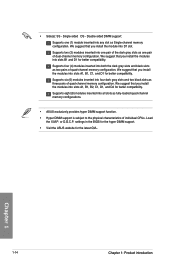
Load the X.M.P. settings in the BIOS for the hyper DIMM support. • Visit the ASUS website for better compatibility. We suggest that you install the module into slots A1, B1, B2, C1, D1, and D2 for better compatibility. We ... of individual CPUs. Supports two (2) modules inserted into four dark gray slots and two black slots as fully-loaded quad-channel memory configurations. • ASUS exclusively provides hyper DIMM support function. • Hyper DIMM support is subject to the physical characteristics of quad-channel memory configuration. We suggest that you...
Load the X.M.P. settings in the BIOS for the hyper DIMM support. • Visit the ASUS website for better compatibility. We suggest that you install the module into slots A1, B1, B2, C1, D1, and D2 for better compatibility. We ... of individual CPUs. Supports two (2) modules inserted into four dark gray slots and two black slots as fully-loaded quad-channel memory configurations. • ASUS exclusively provides hyper DIMM support function. • Hyper DIMM support is subject to the physical characteristics of quad-channel memory configuration. We suggest that you...

User Guide
Page 35
...LEDs for the exact location of the DIAG_DRAM LED. • The DIAG_DRAM LED also lights up due to test one set of failsafe settings. ASUS X99-A/USB 3.1 1-19 Chapter 1 button lights continuously. button does not function under Windows® OS environment. • During the tuning process, the system...continuously. MemOK! button until the DIAG_DRAM LED starts blinking to begin automatic memory compatibility tuning. • Refer to boot and load the BIOS default settings. If the test fails, the system reboots and test the next set is not properly installed. A message will appear ...
...LEDs for the exact location of the DIAG_DRAM LED. • The DIAG_DRAM LED also lights up due to test one set of failsafe settings. ASUS X99-A/USB 3.1 1-19 Chapter 1 button lights continuously. button does not function under Windows® OS environment. • During the tuning process, the system...continuously. MemOK! button until the DIAG_DRAM LED starts blinking to begin automatic memory compatibility tuning. • Refer to boot and load the BIOS default settings. If the test fails, the system reboots and test the next set is not properly installed. A message will appear ...
User Guide
Page 36
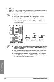
... this switch under Windows® OS environment, the TPU function will use the 5-Way Optimization and TPU feature in the AI Suite 3 application, adjust the BIOS setup program or enable the TPU switch at the same time. 4. Refer to section 1.2.8 Onboard LEDs for the exact location of the TPU LEDs. •...
... this switch under Windows® OS environment, the TPU function will use the 5-Way Optimization and TPU feature in the AI Suite 3 application, adjust the BIOS setup program or enable the TPU switch at the same time. 4. Refer to section 1.2.8 Onboard LEDs for the exact location of the TPU LEDs. •...

User Guide
Page 37
.... • You may change the EPU settings in the software application or BIOS setup program and enable the EPU function at the same time. Refer to automatically detect the current PC loadings and intelligently moderate the power consumption. Chapter 1 ASUS X99-A/USB 3.1 1-21 5. EPU switch Enable this switch to section 1.2.8 Onboard LEDs for the...
.... • You may change the EPU settings in the software application or BIOS setup program and enable the EPU function at the same time. Refer to automatically detect the current PC loadings and intelligently moderate the power consumption. Chapter 1 ASUS X99-A/USB 3.1 1-21 5. EPU switch Enable this switch to section 1.2.8 Onboard LEDs for the...

User Guide
Page 39
ASUS X99-A/USB 3.1 1-23 Chapter 1 You can automatically reset parameter settings to default values. • Due to ...Plug the power cord and turn off is required to pins 2-3. Shut down the key during the boot process and enter BIOS setup to clear the CMOS RTC RAM data. Move the jumper cap from pins 1-2 (default) to enable C.P.R. Removing the... due to overclocking, use the C.P.R. (CPU Parameter Recall) feature. function. Hold down and reboot the system so the BIOS can clear the CMOS memory of date, time, and system setup parameters by erasing the CMOS RTC RAM data. Except ...
ASUS X99-A/USB 3.1 1-23 Chapter 1 You can automatically reset parameter settings to default values. • Due to ...Plug the power cord and turn off is required to pins 2-3. Shut down the key during the boot process and enter BIOS setup to clear the CMOS RTC RAM data. Move the jumper cap from pins 1-2 (default) to enable C.P.R. Removing the... due to overclocking, use the C.P.R. (CPU Parameter Recall) feature. function. Hold down and reboot the system so the BIOS can clear the CMOS memory of date, time, and system setup parameters by erasing the CMOS RTC RAM data. Except ...

User Guide
Page 47
... configuration with the Intel® Rapid Storage Technology through the onboard Intel® X99 chipset. ASUS X99-A/USB 3.1 1-31 Refer to section 3.6.3 PCH Storage Configuration for details. • Before creating a RAID set ...X99 Serial ATA 6 Gb/s connectors (7-pin SATA6G_12, SATA6G_34, SATA6G_5, SATA6G_6/SATAEXPRESS, SATA6G_78, SATA6G_910) These connectors connect to chipset behavior, the SATA6G_78 and SATA6G_910 ports (black) do not support Intel® Rapid Storage Technology and RAID configuration. Chapter 1 • These connectors are set , refer to the manual bundled in the BIOS...
... configuration with the Intel® Rapid Storage Technology through the onboard Intel® X99 chipset. ASUS X99-A/USB 3.1 1-31 Refer to section 3.6.3 PCH Storage Configuration for details. • Before creating a RAID set ...X99 Serial ATA 6 Gb/s connectors (7-pin SATA6G_12, SATA6G_34, SATA6G_5, SATA6G_6/SATAEXPRESS, SATA6G_78, SATA6G_910) These connectors connect to chipset behavior, the SATA6G_78 and SATA6G_910 ports (black) do not support Intel® Rapid Storage Technology and RAID configuration. Chapter 1 • These connectors are set , refer to the manual bundled in the BIOS...

User Guide
Page 51
...8226; DO NOT forget to connect the fan cables to Advanced Mode > Monitor > Chassis Fan 1/4 Q-Fan Control items in BIOS. • The chassis fan connectors support DC and PWM modes. 6. ASUS X99-A/USB 3.1 1-35 To set these fans to DC or PWM, go to the CPU fan connector. Chapter 1 • The ...CPU_FAN connector supports the CPU fan of maximum 1A (12 W) fan power. • The CPU_FAN, CHA_FAN, and EXT_FAN connectors support the ASUS FAN Xpert 3 feature on...
...8226; DO NOT forget to connect the fan cables to Advanced Mode > Monitor > Chassis Fan 1/4 Q-Fan Control items in BIOS. • The chassis fan connectors support DC and PWM modes. 6. ASUS X99-A/USB 3.1 1-35 To set these fans to DC or PWM, go to the CPU fan connector. Chapter 1 • The ...CPU_FAN connector supports the CPU fan of maximum 1A (12 W) fan power. • The CPU_FAN, CHA_FAN, and EXT_FAN connectors support the ASUS FAN Xpert 3 feature on...
User Guide
Page 56
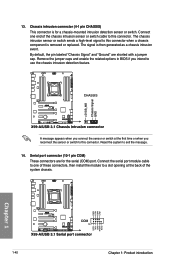
... pin labeled "Chassis Signal" and "Ground" are for a chassis-mounted intrusion detection sensor or switch. Remove the jumper caps and enable the related options in BIOS if you reconnect the sensor or switch to this connector. 13. Serial port connector (10-1 pin COM) These connectors are shorted with a jumper cap. Connect...
... pin labeled "Chassis Signal" and "Ground" are for a chassis-mounted intrusion detection sensor or switch. Remove the jumper caps and enable the related options in BIOS if you reconnect the sensor or switch to this connector. 13. Serial port connector (10-1 pin COM) These connectors are shorted with a jumper cap. Connect...

User Guide
Page 57
...'s high-definition audio capability. • If you want to connect a high-definition or an AC'97 front panel audio module to [HD] or [AC97]. Chapter 1 ASUS X99-A/USB 3.1 1-41 15. Front panel audio connector (10-1 pin AAFP) This connector is for a chassis-mounted front panel audio I /O module cable to this connector, set the...
...'s high-definition audio capability. • If you want to connect a high-definition or an AC'97 front panel audio module to [HD] or [AC97]. Chapter 1 ASUS X99-A/USB 3.1 1-41 15. Front panel audio connector (10-1 pin AAFP) This connector is for a chassis-mounted front panel audio I /O module cable to this connector, set the...

User Guide
Page 69
.... 2. Launch the USB BIOS Flashback Wizard to easily update the BIOS without entering the existing BIOS or operating system. 2.2 BIOS update utility USB BIOS Flashback USB BIOS Flashback allows you to the section 3.11 Updating BIOS in green on the I /O connection for three seconds until the light goes out, indicating that supports USB BIOS Flashback. 3. ASUS X99-A/USB 3.1 2-11 Chapter 2 BIOS Flashback button USB BIOS Flashback port 6. This...
.... 2. Launch the USB BIOS Flashback Wizard to easily update the BIOS without entering the existing BIOS or operating system. 2.2 BIOS update utility USB BIOS Flashback USB BIOS Flashback allows you to the section 3.11 Updating BIOS in green on the I /O connection for three seconds until the light goes out, indicating that supports USB BIOS Flashback. 3. ASUS X99-A/USB 3.1 2-11 Chapter 2 BIOS Flashback button USB BIOS Flashback port 6. This...

User Guide
Page 70
USB BIOS Flashback 6. USB 2.0 ports 78 (bottom port supports USB BIOS Flashback) 9. Optical S/PDIF Out port 5. 2.3 Motherboard rear and audio connections 2.3.1 Rear I /O ports** * and **: Refer to the tables on the next page for LAN port LEDs and audio port definitions. 2-12 Chapter 2: Basic installation USB 3.1 ports E56 (Support USB 3.1 Boost) 7. USB 3.0 ports E2_5 (Supports USB 3.0 Boost) 4. Audio I /O connection Chapter 2 Rear...
USB BIOS Flashback 6. USB 2.0 ports 78 (bottom port supports USB BIOS Flashback) 9. Optical S/PDIF Out port 5. 2.3 Motherboard rear and audio connections 2.3.1 Rear I /O ports** * and **: Refer to the tables on the next page for LAN port LEDs and audio port definitions. 2-12 Chapter 2: Basic installation USB 3.1 ports E56 (Support USB 3.1 Boost) 7. USB 3.0 ports E2_5 (Supports USB 3.0 Boost) 4. Audio I /O connection Chapter 2 Rear...

User Guide
Page 71
...BIOS. Rear Speaker Out 6-channel Line In Front Speaker Out Mic In Center/Subwoofer Rear Speaker Out 8-channel Side Speaker Out Front Speaker Out Mic In Center/Subwoofer Rear Speaker Out Chapter 2 ASUS X99-A/USB 3.1 2-13 • The plugged USB 3.0 device may continue to the USB 2.0 and USB... 3.0 ports are controlled by the xHCI controller. Some legacy USB devices must update their firmware for better compatibility. * LAN...
...BIOS. Rear Speaker Out 6-channel Line In Front Speaker Out Mic In Center/Subwoofer Rear Speaker Out 8-channel Side Speaker Out Front Speaker Out Mic In Center/Subwoofer Rear Speaker Out Chapter 2 ASUS X99-A/USB 3.1 2-13 • The plugged USB 3.0 device may continue to the USB 2.0 and USB... 3.0 ports are controlled by the xHCI controller. Some legacy USB devices must update their firmware for better compatibility. * LAN...
User Guide
Page 74
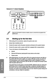
... with ATX power supplies, the system LED lights up . For systems with the last device on . After making all switches are running, the BIOS beeps (refer to the BIOS beep codes table) or additional messages appear on the system front panel case lights up when you turned on the power, the system...
... with ATX power supplies, the system LED lights up . For systems with the last device on . After making all switches are running, the BIOS beeps (refer to the BIOS beep codes table) or additional messages appear on the system front panel case lights up when you turned on the power, the system...


