X99-DELUXE II - Asus
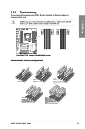
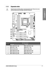
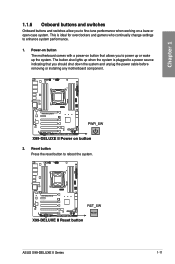
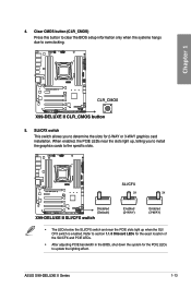
X99-DELUXE II
View Results Below
Free Asus X99-DELUXE II manuals!
Problems with Asus X99-DELUXE II?
Ask a Question
Free Asus X99-DELUXE II manuals!
Problems with Asus X99-DELUXE II?
Ask a Question
Related Manual Pages
Related Videos

2 is Better Than 1? ASUS X99 Deluxe II Review!
Duration: 16:42
Total Views: 122,598
Duration: 16:42
Total Views: 122,598
? ??????? – ??????????? ????? ASUS X99-Deluxe II – ???????? ??? – ?????????
Duration: 4:31
Total Views: 49,275
Duration: 4:31
Total Views: 49,275
Review Mainbaord ASUS x99 Deluxe II |Sakkdafix
Duration: 18:18
Total Views: 107
Duration: 18:18
Total Views: 107
Probleme carte mére asus x99 deluxe II
Duration: 5:19
Total Views: 768
Duration: 5:19
Total Views: 768
ASUS X99 Deluxe II chips on both sides
Duration: 1:11
Total Views: 355
Duration: 1:11
Total Views: 355
Similar Questions

Asus Essence Stx Ii 7.1
I wonder about ASUS Essence STX II 7.1 Does it support DTS-MA and Dolby TrueHD ? There is no info ab...
I wonder about ASUS Essence STX II 7.1 Does it support DTS-MA and Dolby TrueHD ? There is no info ab...
(Posted by jimryen 8 years ago)

