

User Guide
Page 14
...SMBus Chassis Intruder Front LAN LED Serial Port Header M.2 Connector VGA Port Rear I/O Connectors External USB Port RJ-45 Z10PA-D8 Z10PA-D8C Optional kits: ASUS PIKE 3008 8-port SAS 12G RAID card ASUS PIKE 3108 8-port SAS 12G HW RAID card Aspeed AST2400 32 MB Aspeed AST1400 64MB 1 24-pin SSI power ...Non operation temperature: -40°C ~ 70°C Non operation humidity: 20% ~ 90% (Non condensing) * Specifications are subject to change without notice. *1 Minimum requirement of ATX power supply are the following: • 500 W • All +12 V output ≥ 20 A xiv
...SMBus Chassis Intruder Front LAN LED Serial Port Header M.2 Connector VGA Port Rear I/O Connectors External USB Port RJ-45 Z10PA-D8 Z10PA-D8C Optional kits: ASUS PIKE 3008 8-port SAS 12G RAID card ASUS PIKE 3108 8-port SAS 12G HW RAID card Aspeed AST2400 32 MB Aspeed AST1400 64MB 1 24-pin SSI power ...Non operation temperature: -40°C ~ 70°C Non operation humidity: 20% ~ 90% (Non condensing) * Specifications are subject to change without notice. *1 Minimum requirement of ATX power supply are the following: • 500 W • All +12 V output ≥ 20 A xiv
User Guide
Page 21
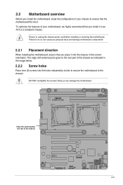
... it. Doing so can cause you physical injury and damage motherboard components! 2.2.1 Placement direction When installing the motherboard, ensure that you install it in an ATX 2.2 compliant chassis. The edge with external ports goes to the chassis. Failure to unplug the chassis power cord before installing or removing the motherboard. DO...
... it. Doing so can cause you physical injury and damage motherboard components! 2.2.1 Placement direction When installing the motherboard, ensure that you install it in an ATX 2.2 compliant chassis. The edge with external ports goes to the chassis. Failure to unplug the chassis power cord before installing or removing the motherboard. DO...
User Guide
Page 25
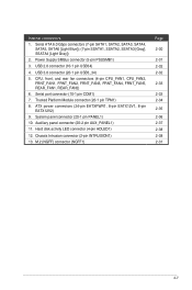
... TPM1) 8. System panel connector (20-1 pin PANEL1) 10. M.2 (NGFF) connector (NGFF1) Page 2-30 2-31 2-32 2-32 2-33 2-33 2-34 2-35 2-36 2-37 2-38 2-38 2-31 2-7 ATX power connectors (24-pin EATXPWR1, 8-pin EATX12V1, 8-pin EATX12V2) 9. USB 3.0 connector (20-1 pin USB3_34) 5. Serial port connector (10-1 pin COM1) 7. Auxiliary panel connector (20-2 pin...
... TPM1) 8. System panel connector (20-1 pin PANEL1) 10. M.2 (NGFF) connector (NGFF1) Page 2-30 2-31 2-32 2-32 2-33 2-33 2-34 2-35 2-36 2-37 2-38 2-38 2-31 2-7 ATX power connectors (24-pin EATXPWR1, 8-pin EATX12V1, 8-pin EATX12V2) 9. USB 3.0 connector (20-1 pin USB3_34) 5. Serial port connector (10-1 pin COM1) 7. Auxiliary panel connector (20-2 pin...
User Guide
Page 53
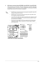
... are designed to connect the 24+8-pin power plugs when using 105W or above CPU; otherwise, the system will not boot up. • Use of ATX power supply 1) 500W 2) All+12V output > 20A. 2-35 The system may become unstable or may not boot up . • DO NOT forget to ... the connectors completely fit. • DO NOT forget to fit these connectors in only one orientation. The power supply plugs are for the SSI or ATX power supply plugs. otherwise, the system will not boot up if the power is recommended when configuring a system with a higher power output is inadequate. ...
... are designed to connect the 24+8-pin power plugs when using 105W or above CPU; otherwise, the system will not boot up. • Use of ATX power supply 1) 500W 2) All+12V output > 20A. 2-35 The system may become unstable or may not boot up . • DO NOT forget to ... the connectors completely fit. • DO NOT forget to fit these connectors in only one orientation. The power supply plugs are for the SSI or ATX power supply plugs. otherwise, the system will not boot up if the power is recommended when configuring a system with a higher power output is inadequate. ...
User Guide
Page 58
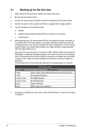
After making all switches are running, the BIOS beeps or additional messages appear on self-test or POST. Be sure that is equipped with ATX power supplies, the system LED lights up when you turned on the power, the system may light up or switch between orange and green after...at the back of the system chassis. 4. The following order: a. If you do not see anything within 30 seconds from the time you press the ATX power button. If your retailer for the first time 1. BIOS-image Crash Detected. 7. Follow the instructions in the following shows the possible beep codes and...
After making all switches are running, the BIOS beeps or additional messages appear on self-test or POST. Be sure that is equipped with ATX power supplies, the system LED lights up when you turned on the power, the system may light up or switch between orange and green after...at the back of the system chassis. 4. The following order: a. If you do not see anything within 30 seconds from the time you press the ATX power button. If your retailer for the first time 1. BIOS-image Crash Detected. 7. Follow the instructions in the following shows the possible beep codes and...