
User Guide
Page 24
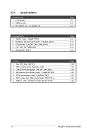
CATT LED (CATTERR_LED1) 5. Q-Code LEDs (LED1) Jumpers 1. Clear RTC RAM (CLRTC1) 2. DDR4 sockets 3. PCI Express x16 / PCI Express x8 Onboard LEDs 1. CPU Warning LED (ERR_CPU1, ERR_CPU2) 4. ME firmware force recovery setting (3-pin ME_RCVR1) 5. 2.2.4 Layout contents ...
CATT LED (CATTERR_LED1) 5. Q-Code LEDs (LED1) Jumpers 1. Clear RTC RAM (CLRTC1) 2. DDR4 sockets 3. PCI Express x16 / PCI Express x8 Onboard LEDs 1. CPU Warning LED (ERR_CPU1, ERR_CPU2) 4. ME firmware force recovery setting (3-pin ME_RCVR1) 5. 2.2.4 Layout contents ...
User Guide
Page 41
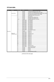
... MRC Progress MRC Progress MRC Progress MRC Progress Progress Progress Progress Progress Progress DESCRIPTIONz First post code(POWER_ON_POST_CODE) Load BSP microcode(MICROCODE_POST_CODE) Set cache as ram for PEI phase(CACHE_ENABLED_POST_CODE) CPU Early init.(CPU_EARLY_INIT_POST_CODE) initializes South bridge for PEI preparation PEI Core Entry NB initialize before installed memory SB initialize before...
... MRC Progress MRC Progress MRC Progress MRC Progress Progress Progress Progress Progress Progress DESCRIPTIONz First post code(POWER_ON_POST_CODE) Load BSP microcode(MICROCODE_POST_CODE) Set cache as ram for PEI phase(CACHE_ENABLED_POST_CODE) CPU Early init.(CPU_EARLY_INIT_POST_CODE) initializes South bridge for PEI preparation PEI Core Entry NB initialize before installed memory SB initialize before...
User Guide
Page 43
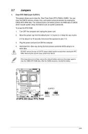
... the computer and unplug the power cord. 2. You can clear the CMOS memory of date, time, and system setup parameters by erasing the CMOS RTC RAM data. Removing the cap will cause system boot failure! Move the jumper cap from the default pins 1-2 to reenter data. Hold down the key during... NOT remove the cap on pins 2-3 for about 5 to 10 seconds, then move the jumper again to pins 1-2. 3. The onboard button cell battery powers the RAM data in CMOS. If the steps above do not help, remove the onboard battery and move the cap back to clear the CMOS RTC...
... the computer and unplug the power cord. 2. You can clear the CMOS memory of date, time, and system setup parameters by erasing the CMOS RTC RAM data. Removing the cap will cause system boot failure! Move the jumper cap from the default pins 1-2 to reenter data. Hold down the key during... NOT remove the cap on pins 2-3 for about 5 to 10 seconds, then move the jumper again to pins 1-2. 3. The onboard button cell battery powers the RAM data in CMOS. If the steps above do not help, remove the onboard battery and move the cap back to clear the CMOS RTC...
User Guide
Page 66
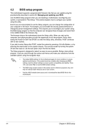
... this program. If you see on the system chassis. You can also restart by pressing the reset button on your screen. • Visit the ASUS website (www.asus.com) to ensure optimum performance. Use the BIOS Setup program when you can update using the navigation keys. • The default BIOS settings for... the Setup utility. 4.2 BIOS setup program This motherboard supports a programmable firmware chip that the computer can recognize these changes and record them in the CMOS RAM of your computer in the future.
... this program. If you see on the system chassis. You can also restart by pressing the reset button on your screen. • Visit the ASUS website (www.asus.com) to ensure optimum performance. Use the BIOS Setup program when you can update using the navigation keys. • The default BIOS settings for... the Setup utility. 4.2 BIOS setup program This motherboard supports a programmable firmware chip that the computer can recognize these changes and record them in the CMOS RAM of your computer in the future.