
Owners Manual
Page 1
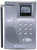
FRS/ Weather Model: FRS-1000 Base Station With NOAA Weather Alert Owner's Manual Customer Service/Service 1-800-290-6650 © 2001 Audiovox Electronics Corp., Hauppauge, NY 11788 Printed in Korea 128-6032
FRS/ Weather Model: FRS-1000 Base Station With NOAA Weather Alert Owner's Manual Customer Service/Service 1-800-290-6650 © 2001 Audiovox Electronics Corp., Hauppauge, NY 11788 Printed in Korea 128-6032
Owners Manual
Page 2
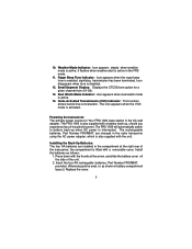
...frequencies. USE OF OTHER BATTERIES WILL CAUSE DAMAGE TO YOUR FRS-1000 WEATHER RADIO TRANSCEIVER. way radio service for a license. less in open areas; Family Radio Service: The Family Radio Service (FRS) 2-way base (fixed) station "transceiver" ("transmitter and receiver") radio has been designed for...in areas with buildings, dense foliage, and mountains. 2 CAUTION NEVER ATTEMPT TO CHARGE ALKALINE OR DRY CELL BATTERIES. AVOID INSTALLING THE FRS-1000 TRANSCEIVER IN AN AREA WHERE IT MAY BE SUBJECTED FOR PROLONGED PERIODS OF TIME TO DIRECT SUNLIGHT OR TEMPERATURES BELOW -4° F (-...
...frequencies. USE OF OTHER BATTERIES WILL CAUSE DAMAGE TO YOUR FRS-1000 WEATHER RADIO TRANSCEIVER. way radio service for a license. less in open areas; Family Radio Service: The Family Radio Service (FRS) 2-way base (fixed) station "transceiver" ("transmitter and receiver") radio has been designed for...in areas with buildings, dense foliage, and mountains. 2 CAUTION NEVER ATTEMPT TO CHARGE ALKALINE OR DRY CELL BATTERIES. AVOID INSTALLING THE FRS-1000 TRANSCEIVER IN AN AREA WHERE IT MAY BE SUBJECTED FOR PROLONGED PERIODS OF TIME TO DIRECT SUNLIGHT OR TEMPERATURES BELOW -4° F (-...
Owners Manual
Page 3
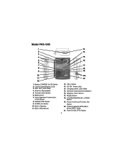
...-in Microphone 13 14 15 16 17 18 19 20 21 12. Weather Alert Button 17. Transmit LED (Green) 6. Voice-Operated Transmission (VOX) Button 8. Model FRS-1000 1 2 3 4 5 6 7 8 9 10 11 12 1. Weather/FRS Button 9. Power On/Off and Function Set Button 20. Up/Down Channel/Volume Buttons 16. phone (MIC) Jacks 21.
...-in Microphone 13 14 15 16 17 18 19 20 21 12. Weather Alert Button 17. Transmit LED (Green) 6. Voice-Operated Transmission (VOX) Button 8. Model FRS-1000 1 2 3 4 5 6 7 8 9 10 11 12 1. Weather/FRS Button 9. Power On/Off and Function Set Button 20. Up/Down Channel/Volume Buttons 16. phone (MIC) Jacks 21.
Owners Manual
Page 4
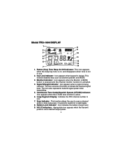
Signal Strength Indicator: Icon appears when a signal is locked. Large Segment Display: Indicates the FRS channel number in use . 7. Key Lock Indicator: Icon appears when keypad is being received. The icon consists of five bars to search for a valid signal. 8. ... the CTCSS tone function is activated. 4. Monitor Indicator: Icon appears when the Monitor (L/MON) button is pressed and the channel monitor function is active. 6. Model FRS-1000 DISPLAY 1 8 2 9 3 10 4 11 5 6 12 13 7 14 1.
Signal Strength Indicator: Icon appears when a signal is locked. Large Segment Display: Indicates the FRS channel number in use . 7. Key Lock Indicator: Icon appears when keypad is being received. The icon consists of five bars to search for a valid signal. 8. ... the CTCSS tone function is activated. 4. Monitor Indicator: Icon appears when the Monitor (L/MON) button is pressed and the channel monitor function is active. 6. Model FRS-1000 DISPLAY 1 8 2 9 3 10 4 11 5 6 12 13 7 14 1.
Owners Manual
Page 5
... Tone Indicator: Icon appears when the roger beep tone is disabled. 12. Small Segment Display: Displays the CTCSS tone option for Your FRS-1000 base station is interrupted. Installing the Back-Up Batteries: The four AA batteries are charged in battery compartment layout.) Replace the cover. 5 Install ...2. the compartment is active in the compartment at the arrow, and slide the battery cover off the side of the transceiver; The FRS-1000 is active. 14. Weather Mode Indicator: Icon appears steady when weather mode is activated. Dual Watch Mode Indicator: Icon appears when ...
... Tone Indicator: Icon appears when the roger beep tone is disabled. 12. Small Segment Display: Displays the CTCSS tone option for Your FRS-1000 base station is interrupted. Installing the Back-Up Batteries: The four AA batteries are charged in battery compartment layout.) Replace the cover. 5 Install ...2. the compartment is active in the compartment at the arrow, and slide the battery cover off the side of the transceiver; The FRS-1000 is active. 14. Weather Mode Indicator: Icon appears steady when weather mode is activated. Dual Watch Mode Indicator: Icon appears when ...
Owners Manual
Page 6
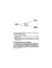
... switch to the ON position. BATTERY COMPARTMENT COVER BATTERY COMPARTMENT COVER ARROW The following guidelines will void the warranty. Charging FRS-1000 Batteries P/N FRSRBAT: The rechargeable batteries, Part Number FRSRBAT, supplied with the base unit. The CHG. Do not mix old and new batteries. 2. LED indicator below the LCD display lights red during... plug to the DC12V jack on the top of time, remove the batteries. Old or leaking batteries can cause damage to be used for the FRS-1000: 1. + BATTERY INSTALLATION - POLARITY + -
... switch to the ON position. BATTERY COMPARTMENT COVER BATTERY COMPARTMENT COVER ARROW The following guidelines will void the warranty. Charging FRS-1000 Batteries P/N FRSRBAT: The rechargeable batteries, Part Number FRSRBAT, supplied with the base unit. The CHG. Do not mix old and new batteries. 2. LED indicator below the LCD display lights red during... plug to the DC12V jack on the top of time, remove the batteries. Old or leaking batteries can cause damage to be used for the FRS-1000: 1. + BATTERY INSTALLATION - POLARITY + -
Owners Manual
Page 8
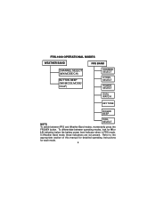
To differentiate between FRS and Weather Band modes, momentarily press the FRS/WX button. In Weather Band mode, these indications are not present. FRS-1000 OPERATIONAL MODES WEATHER BAND FRS BAND CHANNEL SELECT (WX/MODE/CH) BUTTON BEEP (WX/MODE,MODE/ On/oF) CHANNEL SELECT CTCSS SELECT POWER SELECT DUAL WATCH KEY TONE ROGER BEEP CALL SELECT NOTE: To switch between operating modes, look for each mode. 8 Refer to the appropriate section of this manual for detailed operating instructions for HI or LO indication below the battery power level indicator when in FRS mode.
To differentiate between FRS and Weather Band modes, momentarily press the FRS/WX button. In Weather Band mode, these indications are not present. FRS-1000 OPERATIONAL MODES WEATHER BAND FRS BAND CHANNEL SELECT (WX/MODE/CH) BUTTON BEEP (WX/MODE,MODE/ On/oF) CHANNEL SELECT CTCSS SELECT POWER SELECT DUAL WATCH KEY TONE ROGER BEEP CALL SELECT NOTE: To switch between operating modes, look for each mode. 8 Refer to the appropriate section of this manual for detailed operating instructions for HI or LO indication below the battery power level indicator when in FRS mode.
Owners Manual
Page 10
...The Transmit LED will cycle to adjust the unit's settings. Pressing the button will display the relative strength of jacks accepts an Audiovox headset/microphone connector. When receiving an incoming signal, the received signal strength indicator ( ) will call ringer. The MODE button ... mode, pressing this button momentarily will increment the listening volume. Down Channel/Volume Button (15) In the FRS standby mode, pressing this Button momentarily to FRS-1000 Operational Modes. CALL Button (12) The CALL Button can also be used to each mode. Scan/Lock Mode Button ...
...The Transmit LED will cycle to adjust the unit's settings. Pressing the button will display the relative strength of jacks accepts an Audiovox headset/microphone connector. When receiving an incoming signal, the received signal strength indicator ( ) will call ringer. The MODE button ... mode, pressing this button momentarily will increment the listening volume. Down Channel/Volume Button (15) In the FRS standby mode, pressing this Button momentarily to FRS-1000 Operational Modes. CALL Button (12) The CALL Button can also be used to each mode. Scan/Lock Mode Button ...
Owners Manual
Page 11
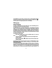
...to the next higher main channel number. - Before transmitting on that is clear. Press the Down Button ( ) briefly to move to communicate with Audiovox FRS and compatible units is locked, the ( ) icon will appear in the upper right corner of 38 Sub-Frequencies. The 11 If there is ...the LCD display panel. and hold Button for more than 1 second to another party on the same main channel using the same subcode. The FRS-1000 has 14 channels (frequencies 1-14) indicated by the large digits on the same frequency. When the keypad is possible on the selected channel,...
...to the next higher main channel number. - Before transmitting on that is clear. Press the Down Button ( ) briefly to move to communicate with Audiovox FRS and compatible units is locked, the ( ) icon will appear in the upper right corner of 38 Sub-Frequencies. The 11 If there is ...the LCD display panel. and hold Button for more than 1 second to another party on the same main channel using the same subcode. The FRS-1000 has 14 channels (frequencies 1-14) indicated by the large digits on the same frequency. When the keypad is possible on the selected channel,...
Owners Manual
Page 17
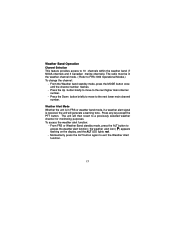
... number. Press any key except the PTT button. Press the Down button briefly to move to the next higher main channel number. - From FRS or Weather Band standby mode, press the ALT button to exit the Weather Alert function. 17 the weather alert icon ( ) appears flashing on...channel mode. ( Refer to a previously selected weather channel for monitoring purposes. The radio must be in FRS or weather band mode, if a weather alert signal is received, the unit will then revert to FRS-1000 Operational Modes.) To change the channel: - The unit will generate a warning tone. Press the Up...
... number. Press any key except the PTT button. Press the Down button briefly to move to the next higher main channel number. - From FRS or Weather Band standby mode, press the ALT button to exit the Weather Alert function. 17 the weather alert icon ( ) appears flashing on...channel mode. ( Refer to a previously selected weather channel for monitoring purposes. The radio must be in FRS or weather band mode, if a weather alert signal is received, the unit will then revert to FRS-1000 Operational Modes.) To change the channel: - The unit will generate a warning tone. Press the Up...
Owners Manual
Page 18
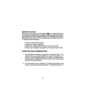
... may be talking on any of the battery ( ) icon appear(s) flashing on a "take turns" basis. The FRS-1000 14 channels are shared on the LCD panel, recharge unit or install new Audiovox approved rechargeable batteries. The FRS-1000 has been designed to maximize performance and improve transmission range to contacting your authorized service center. To...
... may be talking on any of the battery ( ) icon appear(s) flashing on a "take turns" basis. The FRS-1000 14 channels are shared on the LCD panel, recharge unit or install new Audiovox approved rechargeable batteries. The FRS-1000 has been designed to maximize performance and improve transmission range to contacting your authorized service center. To...
