Installation Guide
Page 3
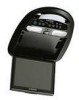
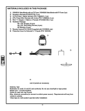
... use a test light or logic probe) Marker pen - MATERIALS INCLUDED IN THIS PACKAGE: 1) VOH681A Video Monitor with out TV Tuner / VOH682A Video Monitor with TV Tuner (1 pc) 2) Accessory Harness (P/N 8010730) (1 pc) 3) 12 Pin Power / Signal harness (P/N 112B2821) (1 pc) 4) 2 Pin Power Wire Harness with choke (P/N 112B2824) (1 pc) 5) RCA "Y" Adapter (1 Male to 2 Female) (P/N 0892165) (1 pc) 6) Hardware Package #4 x 3/8" Screws...
... use a test light or logic probe) Marker pen - MATERIALS INCLUDED IN THIS PACKAGE: 1) VOH681A Video Monitor with out TV Tuner / VOH682A Video Monitor with TV Tuner (1 pc) 2) Accessory Harness (P/N 8010730) (1 pc) 3) 12 Pin Power / Signal harness (P/N 112B2821) (1 pc) 4) 2 Pin Power Wire Harness with choke (P/N 112B2824) (1 pc) 5) RCA "Y" Adapter (1 Male to 2 Female) (P/N 0892165) (1 pc) 6) Hardware Package #4 x 3/8" Screws...

Installation Guide
Page 4
... 3). 5) Route the wiring harnesses throughout the vehicle as necessary. (Refer to the Wiring Diagrams on the video monitor itself . System 3: Video Monitor (VOH681A), VCP, 2nd VCP (or other type of mounting. Refer to the wiring diagram on p7. -The VOH681A and VOH 682A video systems are fully installed.... room. 6) Remove all A/V system components from sharp edges and is not intended for horizontal, drop down installation. System 2: Video Monitor with tuner (VOH682A), VCP -Same as follows: a) Remote headphone jacks can be added as system 1, but TV antenna must be added (AN-300...
... 3). 5) Route the wiring harnesses throughout the vehicle as necessary. (Refer to the Wiring Diagrams on the video monitor itself . System 3: Video Monitor (VOH681A), VCP, 2nd VCP (or other type of mounting. Refer to the wiring diagram on p7. -The VOH681A and VOH 682A video systems are fully installed.... room. 6) Remove all A/V system components from sharp edges and is not intended for horizontal, drop down installation. System 2: Video Monitor with tuner (VOH682A), VCP -Same as follows: a) Remote headphone jacks can be added as system 1, but TV antenna must be added (AN-300...

Installation Guide
Page 8
...Gray (Left+) IR LED: Clean the IR Receiver Window on the Video Monitor. 6) Connect the wired RF Modulator and / or the remote headphone jacks to the video monitor if those options are being included. 7) Connect power harness to vehicle's electrical system by tapping into an accessory hot line. 8) Reinstall... 4) Pull the wire tie loop tight and cut off the excess. 5) Connect the 12 pin harness to Instructions with Non-Stereo Installations Item# 35b 1) Make the connections to the video monitor system using the 2 screws. 9) Verify all functions of the System before final mounting of the ...
...Gray (Left+) IR LED: Clean the IR Receiver Window on the Video Monitor. 6) Connect the wired RF Modulator and / or the remote headphone jacks to the video monitor if those options are being included. 7) Connect power harness to vehicle's electrical system by tapping into an accessory hot line. 8) Reinstall... 4) Pull the wire tie loop tight and cut off the excess. 5) Connect the 12 pin harness to Instructions with Non-Stereo Installations Item# 35b 1) Make the connections to the video monitor system using the 2 screws. 9) Verify all functions of the System before final mounting of the ...

Installation Guide
Page 9
... an accessory hot line. 8) Reinstall PCB cover using a second Source Component Harness (purchased separately, part number: 8010730). Note: Installation Guide covers models : VOH682A. -7- VOH682A Note: cables exiting the pod should be connected to the video monitor system using the 2 screws. 9) Connect and mount the Television antenna, or...remain attached at to rivet hole). 3) Insert the Circular Mini-Din Connector of the monitor). left Mini Din) 4= Aux Input (RCA jacks on the face of the source Component Harness through the wire tie loop on the main PCB and into the Mini-Din Connector ...
... an accessory hot line. 8) Reinstall PCB cover using a second Source Component Harness (purchased separately, part number: 8010730). Note: Installation Guide covers models : VOH682A. -7- VOH682A Note: cables exiting the pod should be connected to the video monitor system using the 2 screws. 9) Connect and mount the Television antenna, or...remain attached at to rivet hole). 3) Insert the Circular Mini-Din Connector of the monitor). left Mini Din) 4= Aux Input (RCA jacks on the face of the source Component Harness through the wire tie loop on the main PCB and into the Mini-Din Connector ...

Installation Guide
Page 11
...the wired RF modulator is selected (i.e.: 1,2,3 or 4). Otherwise, verify all connections per the wiring diagram on Monitor Red / black - Verify that power to the sensor window of the source component harness. Verify that the correct source is on TV Stations (Tuner Version Only) -Press Auto Program button. Verify... is facing, distance from known good ground to the nature of color. Lamp common Purple / brown - Verify connections at 2 pin Power Harness behind video monitor. Static on . (Refer to the tuner. No Infrared remote functions for VCP (or other component). -9-
...the wired RF modulator is selected (i.e.: 1,2,3 or 4). Otherwise, verify all connections per the wiring diagram on Monitor Red / black - Verify that power to the sensor window of the source component harness. Verify that the correct source is on TV Stations (Tuner Version Only) -Press Auto Program button. Verify... is facing, distance from known good ground to the nature of color. Lamp common Purple / brown - Verify connections at 2 pin Power Harness behind video monitor. Static on . (Refer to the tuner. No Infrared remote functions for VCP (or other component). -9-