Installation Guide
Page 3
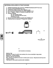
... Monitor with out TV Tuner / VOH682A Video Monitor with TV Tuner (1 pc) 2) Accessory Harness (P/N 8010730) (1 pc) 3) 12 Pin Power / Signal harness (P/N 112B2821) (1 pc) 4) 2 Pin Power Wire Harness with choke (P/N 112B2824) (1 pc) 5) RCA "Y" Adapter (1 Male to 2 Female) (P/N 0892165) (1 pc) 6) Hardware Package #4 x 3/8" Screws (12 pcs) #8 x 5/8" Self Drilling Screws (4 pcs) #8 Washers (4 pcs) 7) Remote Control (P/N 1361612 supplied with VOH682A...
... Monitor with out TV Tuner / VOH682A Video Monitor with TV Tuner (1 pc) 2) Accessory Harness (P/N 8010730) (1 pc) 3) 12 Pin Power / Signal harness (P/N 112B2821) (1 pc) 4) 2 Pin Power Wire Harness with choke (P/N 112B2824) (1 pc) 5) RCA "Y" Adapter (1 Male to 2 Female) (P/N 0892165) (1 pc) 6) Hardware Package #4 x 3/8" Screws (12 pcs) #8 x 5/8" Self Drilling Screws (4 pcs) #8 Washers (4 pcs) 7) Remote Control (P/N 1361612 supplied with VOH682A...

Installation Guide
Page 4
...become familiar with tuner (VOH682A), VCP -Same as follows: a) Remote headphone jacks can be located. It is best done BEFORE, components have built-in such a manner that are possible with the VOH681A and VOH 682A series Drop Down Video Systems: System 1: Video Monitor without tuner (VOH681A), VCP.... -All wiring necessary is routed in game/camcorder inputs (the A/V input jacks on p7. -The VOH681A and VOH 682A video systems are connected into the vehicle...
...become familiar with tuner (VOH682A), VCP -Same as follows: a) Remote headphone jacks can be located. It is best done BEFORE, components have built-in such a manner that are possible with the VOH681A and VOH 682A series Drop Down Video Systems: System 1: Video Monitor without tuner (VOH681A), VCP.... -All wiring necessary is routed in game/camcorder inputs (the A/V input jacks on p7. -The VOH681A and VOH 682A video systems are connected into the vehicle...

Installation Guide
Page 8
... using a second source component harness (purchased separately, part number: 8010730). VOH681A Note: cables exiting the pod should be connected to the video monitor system using the 2 screws. 9) Verify all functions of the System before final mounting of the finished assembly. TO FACTORY RADIO Red: +12...off the excess. 5) Connect the 12 pin harness to the mating connector on the Video Monitor. 6) Connect the wired RF Modulator and / or the remote headphone jacks to the video monitor if those options are being included. 7) Connect power harness to vehicle's electrical system by tapping...
... using a second source component harness (purchased separately, part number: 8010730). VOH681A Note: cables exiting the pod should be connected to the video monitor system using the 2 screws. 9) Verify all functions of the System before final mounting of the finished assembly. TO FACTORY RADIO Red: +12...off the excess. 5) Connect the 12 pin harness to the mating connector on the Video Monitor. 6) Connect the wired RF Modulator and / or the remote headphone jacks to the video monitor if those options are being included. 7) Connect power harness to vehicle's electrical system by tapping...

Installation Guide
Page 9
...main PCB) 2= Tuner 3= 2nd VCP (or game or future DVD, etc..... Note: Installation Guide covers models : VOH682A. -7- A/V Source Definitions: 1= VCP (right Mini Din on the face of the monitor). Note: A second VCP or other A/V Component can be routed as in steps 2 and 3 above. RCA-Female ...remote headphone jacks to the video monitor if those options are being included. 7) Connect power harness to IR Window on the Face of the VCP. Remove Adhesive Backing and Apply IR LED to vehicle's electrical system by tapping into the second Mini-Din connector on the main PCB as shown. VOH682A...
...main PCB) 2= Tuner 3= 2nd VCP (or game or future DVD, etc..... Note: Installation Guide covers models : VOH682A. -7- A/V Source Definitions: 1= VCP (right Mini Din on the face of the monitor). Note: A second VCP or other A/V Component can be routed as in steps 2 and 3 above. RCA-Female ...remote headphone jacks to the video monitor if those options are being included. 7) Connect power harness to IR Window on the Face of the VCP. Remove Adhesive Backing and Apply IR LED to vehicle's electrical system by tapping into the second Mini-Din connector on the main PCB as shown. VOH682A...

Installation Guide
Page 11
...Picture, but no sound -Push and hold the volume up or CH down. No Infrared remote functions for VCP (or other component). -9- Verify connections at 2 pin Power Harness behind video monitor. Then press CH up button until sound is property attached to the correct channel, and...per the wiring diagram on and playing a known good media (such as a videotape). These conditions may adversely affect TV reception. Static on Monitor Red / black - Negative Switched Dome lighting To 12 pin connector on TV Stations (Tuner Version Only) -Press Auto Program button. Verify that...
...Picture, but no sound -Push and hold the volume up or CH down. No Infrared remote functions for VCP (or other component). -9- Verify connections at 2 pin Power Harness behind video monitor. Then press CH up button until sound is property attached to the correct channel, and...per the wiring diagram on and playing a known good media (such as a videotape). These conditions may adversely affect TV reception. Static on Monitor Red / black - Negative Switched Dome lighting To 12 pin connector on TV Stations (Tuner Version Only) -Press Auto Program button. Verify that...

