
Service Guide
Page 3
... Diagram 2-2 Chapter 3 Theory of Operation 3-1 3.1 Fundamental of Optic Process 3-1 3.2 Scan Process 3-2 Chapter 4 Mechanism 4-5 4.1 Optics Module 4-5 4.2 Transmission Module 4-8 Chapter 5 Electrical Systems 5-1 5.1 Overview 5-1 5.2 SCSI Interface 5-5 5.3 Scanner Controller (ASIC & µP 5-7 5.4 Analog Circuits 5-8 5.5 CCD Head/Elements 5-9 5.6 Main Flow Chart of Film Scanner 5-10 5.7 Connectors of Scanner 2740S 5-11 Table of Contents API Confidential i No Copy/Reproduction allowed
... Diagram 2-2 Chapter 3 Theory of Operation 3-1 3.1 Fundamental of Optic Process 3-1 3.2 Scan Process 3-2 Chapter 4 Mechanism 4-5 4.1 Optics Module 4-5 4.2 Transmission Module 4-8 Chapter 5 Electrical Systems 5-1 5.1 Overview 5-1 5.2 SCSI Interface 5-5 5.3 Scanner Controller (ASIC & µP 5-7 5.4 Analog Circuits 5-8 5.5 CCD Head/Elements 5-9 5.6 Main Flow Chart of Film Scanner 5-10 5.7 Connectors of Scanner 2740S 5-11 Table of Contents API Confidential i No Copy/Reproduction allowed
Service Guide
Page 4
... CCD Head 6-3 Chapter 7 Maintenance 7-1 7.1 Precaution 7-1 7.2 Housing Section 7-1 7.3 Transmission Section 7-3 7.4 PCB-frame Section 7-5 7.5 Panel Board Section 7-6 7.6 About Resolution 7-7 Appendix A Frequently Asked Questions A-1 A.1 General Questions A-1 A.2 MiraPhoto A-2 A.3 Hardware (Scanner A-6 A.4 Others A-9 ii API Confidential Table of Contents No Copy/Reproduction allowed
... CCD Head 6-3 Chapter 7 Maintenance 7-1 7.1 Precaution 7-1 7.2 Housing Section 7-1 7.3 Transmission Section 7-3 7.4 PCB-frame Section 7-5 7.5 Panel Board Section 7-6 7.6 About Resolution 7-7 Appendix A Frequently Asked Questions A-1 A.1 General Questions A-1 A.2 MiraPhoto A-2 A.3 Hardware (Scanner A-6 A.4 Others A-9 ii API Confidential Table of Contents No Copy/Reproduction allowed
Service Guide
Page 7
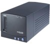
...-reflection optical design for a undistorted scan image Auto-loading mechanism can preview / scan six frames of the professional film scanner features. 1.1 Features 2700 × 2700 dpi optical resolution 36-bits, over 68.7 million colors for accurate color registration All software with... this scanner is Year 2000 compliant Implement DICE technology (Digital defect correction technology). The first film scanner in one time 3.2D high dynamic range for greater color fertility 3-channel ASIC and ...
...-reflection optical design for a undistorted scan image Auto-loading mechanism can preview / scan six frames of the professional film scanner features. 1.1 Features 2700 × 2700 dpi optical resolution 36-bits, over 68.7 million colors for accurate color registration All software with... this scanner is Year 2000 compliant Implement DICE technology (Digital defect correction technology). The first film scanner in one time 3.2D high dynamic range for greater color fertility 3-channel ASIC and ...

Service Guide
Page 9
... batch scan 4 units) Filmstrip 35mm size (Max. Chapter 2 Specifications and Section Names This chapter lists the specifications and section names of the film scanner. 2.1 Specifications Machine Type Professional film scanner Scan Method 3 pass , color CCD Scan Mode grayscale 12 bits/pixel (4096 levels of gray) color 48 bits/pixel (over 68.7 billion...
... batch scan 4 units) Filmstrip 35mm size (Max. Chapter 2 Specifications and Section Names This chapter lists the specifications and section names of the film scanner. 2.1 Specifications Machine Type Professional film scanner Scan Method 3 pass , color CCD Scan Mode grayscale 12 bits/pixel (4096 levels of gray) color 48 bits/pixel (over 68.7 billion...
Service Guide
Page 10
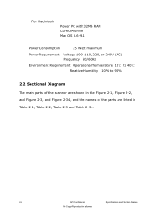
For Macintosh Power PC with 32MB RAM CD-ROM drive Mac OS 8.6-9.1 Power Consumption 25 Watt maximum Power Requirement Voltage 100, 110, 220, or 240V (AC) Frequency 50/60Hz Environment Requirement Operational Temperature 10℃ to 40℃ Relative Humidity 10% to 90% 2.2 Sectional Diagram The main parts of the scanner are shown in the Figure 2-1, Figure 2-2, and Figure 2-3, and Figure 2-34, and the names of the parts are listed in Table 2-1, Table 2-2, Table 2-3 and Table 2-34. 2-2 API Confidential Specifications and Section Names No Copy/Reproduction allowed
For Macintosh Power PC with 32MB RAM CD-ROM drive Mac OS 8.6-9.1 Power Consumption 25 Watt maximum Power Requirement Voltage 100, 110, 220, or 240V (AC) Frequency 50/60Hz Environment Requirement Operational Temperature 10℃ to 40℃ Relative Humidity 10% to 90% 2.2 Sectional Diagram The main parts of the scanner are shown in the Figure 2-1, Figure 2-2, and Figure 2-3, and Figure 2-34, and the names of the parts are listed in Table 2-1, Table 2-2, Table 2-3 and Table 2-34. 2-2 API Confidential Specifications and Section Names No Copy/Reproduction allowed

Service Guide
Page 15
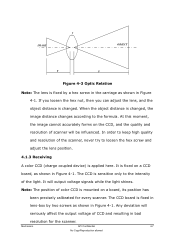
... intensity of light to obtain a proportionally reduced image. Chapter 3 Theory of Operation This chapter describes the optic process and the scan sequences of the Film Scanner. 3.1 Fundamental of Optic Process There are data for the optic process: Auto-Focusing, Imaging and Receiving. 3.1.1 Auto Focusing By moving lens cartridge forward/backward the...
... intensity of light to obtain a proportionally reduced image. Chapter 3 Theory of Operation This chapter describes the optic process and the scan sequences of the Film Scanner. 3.1 Fundamental of Optic Process There are data for the optic process: Auto-Focusing, Imaging and Receiving. 3.1.1 Auto Focusing By moving lens cartridge forward/backward the...

Service Guide
Page 16
... reads in holder to be -scanned object (Slide/Film) into holder and gently insert into holder insertion slot. Then the images are supplied with film scanner: filmstrip and slide holders. 3.2.2 Auto-Focus First the holder will do your scanning. 3-2 API Confidential Theory of holders are shown on the screen. 3.2.4 Pick Target...
... reads in holder to be -scanned object (Slide/Film) into holder and gently insert into holder insertion slot. Then the images are supplied with film scanner: filmstrip and slide holders. 3.2.2 Auto-Focus First the holder will do your scanning. 3-2 API Confidential Theory of holders are shown on the screen. 3.2.4 Pick Target...

Service Guide
Page 19
Figure 4-1 Detail Parts of these mechanisms. The scanner's mechanism can exactly form an image and transform light energy to compose optics module are showed as below (Figure 4-1). Chapter 4 Mechanism This chapter illustrates the mechanisms of the film scanner and describes the functions of Scan Module Mechanism API Confidential 4-5 No Copy/Reproduction allowed This module ensures that the object can be divided into two major departments: ※ Optics Module ※ Transmission Module 4.1 Optics Module The parts to voltage signal, which is critical for the image management.
Figure 4-1 Detail Parts of these mechanisms. The scanner's mechanism can exactly form an image and transform light energy to compose optics module are showed as below (Figure 4-1). Chapter 4 Mechanism This chapter illustrates the mechanisms of the film scanner and describes the functions of Scan Module Mechanism API Confidential 4-5 No Copy/Reproduction allowed This module ensures that the object can be divided into two major departments: ※ Optics Module ※ Transmission Module 4.1 Optics Module The parts to voltage signal, which is critical for the image management.
Service Guide
Page 21
... CCD, and the quality and resolution of CCD and resulting in Figure 4-1. It is fixed on a board, its position has been precisely calibrated for the scanner. The CCD board is fixed in lens-box by a hex screw in the carriage as shown in bad resolution for every... scanner. The CCD is changed , the image distance changes according to the intensity of color CCD is mounted on a CCD board, as shown in Figure 4-1. Any ...
... CCD, and the quality and resolution of CCD and resulting in Figure 4-1. It is fixed on a board, its position has been precisely calibrated for the scanner. The CCD board is fixed in lens-box by a hex screw in the carriage as shown in bad resolution for every... scanner. The CCD is changed , the image distance changes according to the intensity of color CCD is mounted on a CCD board, as shown in Figure 4-1. Any ...

Service Guide
Page 23
...board and Sensor board . Through functional partitions, the whole scanner system can be divided into 3 main modules as shown in figure 5-1. 5.1.1 Functional Overview The whole scanner system can be divided into 6 parts : ASIC Scanner Controller, Analog Circuits, CCD Module, Power supply and Inverter... Systems API Confidential 5-1 No Copy/Reproduction allowed Power Board Host Computer SCSI Interface Cable MainBoard ASIC Scanner Controller Analog Circuits ICE Function CCD module CCD,Inverter,Lamp, Home Sensor Elements (Line motor) Figure 5-1 Electrical Systems Overview ...
...board and Sensor board . Through functional partitions, the whole scanner system can be divided into 3 main modules as shown in figure 5-1. 5.1.1 Functional Overview The whole scanner system can be divided into 6 parts : ASIC Scanner Controller, Analog Circuits, CCD Module, Power supply and Inverter... Systems API Confidential 5-1 No Copy/Reproduction allowed Power Board Host Computer SCSI Interface Cable MainBoard ASIC Scanner Controller Analog Circuits ICE Function CCD module CCD,Inverter,Lamp, Home Sensor Elements (Line motor) Figure 5-1 Electrical Systems Overview ...

Service Guide
Page 24
.../Reproduction allowed Running in normal mode ,the light source(white light) comes from a Lamp at the bottom of the main board. The I /O Module Figure 5-2 Film Scanner System Block Diagram When running in ICE mode is almost the same as normal mode , except for light source coming from CCD (Charge Coupled Device... electrical charges via photo-diodes, then these charges are captured from both the ICE Function and Lamp. The main module is composed of the 2740S scanner.
.../Reproduction allowed Running in normal mode ,the light source(white light) comes from a Lamp at the bottom of the main board. The I /O Module Figure 5-2 Film Scanner System Block Diagram When running in ICE mode is almost the same as normal mode , except for light source coming from CCD (Charge Coupled Device... electrical charges via photo-diodes, then these charges are captured from both the ICE Function and Lamp. The main module is composed of the 2740S scanner.
Service Guide
Page 25
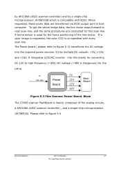
...+16V. It integrates a DC/AC inverter into the required power sources. A home sensor is mainly composed of the line-motor. by AP2106A (ASIC scanner controller) and by a single-chip microprocessor: W78E516B which is co-operated with 8052. Please refer to high-frequency (~30K) AC voltage (~400 V, ...Electrical Systems API Confidential 5-3 No Copy/Reproduction allowed AC 100~240V Power Board 5V 12V 12V 16V Main Board Figure 5-3 Film Scanner Power Board. The Power board ( please refer to host computer. When requested, these pixels data are conducted for this board, for the ...
...+16V. It integrates a DC/AC inverter into the required power sources. A home sensor is mainly composed of the line-motor. by AP2106A (ASIC scanner controller) and by a single-chip microprocessor: W78E516B which is co-operated with 8052. Please refer to high-frequency (~30K) AC voltage (~400 V, ...Electrical Systems API Confidential 5-3 No Copy/Reproduction allowed AC 100~240V Power Board 5V 12V 12V 16V Main Board Figure 5-3 Film Scanner Power Board. The Power board ( please refer to host computer. When requested, these pixels data are conducted for this board, for the ...
Service Guide
Page 26
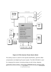
...AP2106A is used for CCD signals amplification, gain/DC offset compensation and digitizing the pixel signals. Block The analog circuits is used for managing the scanner including analog circuits timing, stepping motors(line motor) timing , CCD timing, RAM/ROM timing, and also SCSI 5-4 API Confidential Electrical Systems ...SCSI slave controller & interface Aux Ports( for Motors ) Addr. Bus Data Bus SYSTEM / DATA RAM SCSI I/F Line Motor Driver (6219) Figure 5-4 Film Scanner Power Board. Analog Circuit ASP ADC Bus CPU With ROM W78E516 IR BD CLOCK 16 MHz CCD Video Output Sync.
...AP2106A is used for CCD signals amplification, gain/DC offset compensation and digitizing the pixel signals. Block The analog circuits is used for managing the scanner including analog circuits timing, stepping motors(line motor) timing , CCD timing, RAM/ROM timing, and also SCSI 5-4 API Confidential Electrical Systems ...SCSI slave controller & interface Aux Ports( for Motors ) Addr. Bus Data Bus SYSTEM / DATA RAM SCSI I/F Line Motor Driver (6219) Figure 5-4 Film Scanner Power Board. Analog Circuit ASP ADC Bus CPU With ROM W78E516 IR BD CLOCK 16 MHz CCD Video Output Sync.

Service Guide
Page 27
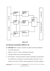
.... The single-chip microprocessor, W78E516 fetches its programs from it will be turned off if defined time-out has reached before the 2740S scanner system receives any command since last command. To scan an image, the host computer sends a series of the following items: a host...Cable(shield), and AP2106A(built in SCSI interface).The illustration is shown in ASIC AP2106A. During preparing and scanning, it . The communication between scanner and HOST computer. It is built in figure 5-5. Then, the host will send several READ commands to control the startup/initialization, and ...
.... The single-chip microprocessor, W78E516 fetches its programs from it will be turned off if defined time-out has reached before the 2740S scanner system receives any command since last command. To scan an image, the host computer sends a series of the following items: a host...Cable(shield), and AP2106A(built in SCSI interface).The illustration is shown in ASIC AP2106A. During preparing and scanning, it . The communication between scanner and HOST computer. It is built in figure 5-5. Then, the host will send several READ commands to control the startup/initialization, and ...
Service Guide
Page 28
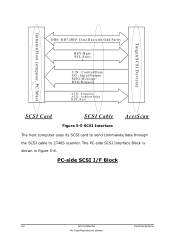
Target(SCSI D evices) Initiator(Host com puter, PC/M ac) DB0~DB7,DBP: Data Bus with Odd Parity B SY :B u sy SEL:Selec t C/D :Control/Data I /F Block 5-6 API Confidential Electrical Systems No Copy/Reproduction allowed PC-side SCSI I /O : Input/Output M SG:M essage REQ :Request ATN: Attention A C K : A cknow ledge RST: Rest SCSI Card SCSI Cable AcerScan Figure 5-5 SCSI Interface The host computer uses its SCSI card to send commands/data through the SCSI cable to 2740S scanner. The PC-side SCSI Interface Block is shown in figure 5-6.
Target(SCSI D evices) Initiator(Host com puter, PC/M ac) DB0~DB7,DBP: Data Bus with Odd Parity B SY :B u sy SEL:Selec t C/D :Control/Data I /F Block 5-6 API Confidential Electrical Systems No Copy/Reproduction allowed PC-side SCSI I /O : Input/Output M SG:M essage REQ :Request ATN: Attention A C K : A cknow ledge RST: Rest SCSI Card SCSI Cable AcerScan Figure 5-5 SCSI Interface The host computer uses its SCSI card to send commands/data through the SCSI cable to 2740S scanner. The PC-side SCSI Interface Block is shown in figure 5-6.
Service Guide
Page 29
Figure 5-6 5.3 Scanner Controller (ASIC & µP) The AP2106A (ASIC scanner controller) includes the following features: 1. 12-bit ADC data input. 2. CPU interface: This ASIC provides an 8051-compatible microprocessor bus interface for firmware updating. A programmable color CCD timing generator. 4. Support 1-color or 3-color simultaneous scanning. 3. Electrical Systems API Confidential 5-7 No Copy/Reproduction allowed It also provides a function of memory space swapping for connecting to an external 8051 series MCU.
Figure 5-6 5.3 Scanner Controller (ASIC & µP) The AP2106A (ASIC scanner controller) includes the following features: 1. 12-bit ADC data input. 2. CPU interface: This ASIC provides an 8051-compatible microprocessor bus interface for firmware updating. A programmable color CCD timing generator. 4. Support 1-color or 3-color simultaneous scanning. 3. Electrical Systems API Confidential 5-7 No Copy/Reproduction allowed It also provides a function of memory space swapping for connecting to an external 8051 series MCU.

Service Guide
Page 31
...API Confidential 5-9 No Copy/Reproduction allowed The image are described in figure 5-8 A m plifier C olor C C D + 12V R egulator M ain B oard Figure 5-8 Film Scanner CCD Board 5.5.1 Line Motor Driver The Line Motor is driven by the L6219. Given the clock pulses and the necessary power, it is very easy... to do the home positioning job, when the 2740S scanner is amplified and transmitted into sampled voltage. As illustrated in figure 5-7. 5.5 CCD Head/Elements This section describes the CCD head module, ...
...API Confidential 5-9 No Copy/Reproduction allowed The image are described in figure 5-8 A m plifier C olor C C D + 12V R egulator M ain B oard Figure 5-8 Film Scanner CCD Board 5.5.1 Line Motor Driver The Line Motor is driven by the L6219. Given the clock pulses and the necessary power, it is very easy... to do the home positioning job, when the 2740S scanner is amplified and transmitted into sampled voltage. As illustrated in figure 5-7. 5.5 CCD Head/Elements This section describes the CCD head module, ...
Service Guide
Page 32
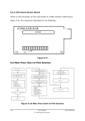
.../Home Sensor Board There is as following. 2740S CC D PC B CCD J1 Figure 5-9 5.6 Main Flow Chart of Film Scanner 5-10 API Confidential No Copy/Reproduction allowed Electrical Systems test analog processor ICs Check burn-in test Initial communication mode Next scan...scanning timing and handshaking timing *) End of scan Next scan Stop (power-off) Figure 5-10 Main Flow Chart of Film Scanner Start (power-on the CCD board in 2740S scanner (referring to host "START SCAN" command Calibration Adjust scanning parameters: 1. Initial system and CPU parameter 2. Reset communication mode System...
.../Home Sensor Board There is as following. 2740S CC D PC B CCD J1 Figure 5-9 5.6 Main Flow Chart of Film Scanner 5-10 API Confidential No Copy/Reproduction allowed Electrical Systems test analog processor ICs Check burn-in test Initial communication mode Next scan...scanning timing and handshaking timing *) End of scan Next scan Stop (power-off) Figure 5-10 Main Flow Chart of Film Scanner Start (power-on the CCD board in 2740S scanner (referring to host "START SCAN" command Calibration Adjust scanning parameters: 1. Initial system and CPU parameter 2. Reset communication mode System...
Service Guide
Page 33
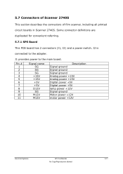
...) and a power switch. J2 is connected to the main board. J1 provides power to the adapter. 5.7 Connectors of Scanner 2740S This section describes the connectors of film scanner, including all printed circuit boards in Scanner 2740S. Pin # 1 2 3 4 5 6 7 8 9 10 11 Signal name SG SG SG +15V +15V +5V +5V D12V SG M12V M12V Description...
...) and a power switch. J2 is connected to the main board. J1 provides power to the adapter. 5.7 Connectors of Scanner 2740S This section describes the connectors of film scanner, including all printed circuit boards in Scanner 2740S. Pin # 1 2 3 4 5 6 7 8 9 10 11 Signal name SG SG SG +15V +15V +5V +5V D12V SG M12V M12V Description...

Service Guide
Page 34
Pin # 1 2 3 4 Signal name LM1A LM1B LM2A LM2B Description Line motor pulse phase 1 of coil A Line motor pulse phase 1 of coil B Line motor pulse phase 2 of coil A Line motor pulse phase 2 of Film Scanner Connector J1 on Scanner 2740S MainBoard J1 is connected to the line motor to drive the stepping motor. J11 5.7.2 MainBoard J1 J13 J4 ASP RAM ASIC CPU 78e516 ASIC MOTOR DRIVER Host J2 Figure 5-11 Main Board of coil B 5-12 API Confidential No Copy/Reproduction allowed Electrical Systems
Pin # 1 2 3 4 Signal name LM1A LM1B LM2A LM2B Description Line motor pulse phase 1 of coil A Line motor pulse phase 1 of coil B Line motor pulse phase 2 of coil A Line motor pulse phase 2 of Film Scanner Connector J1 on Scanner 2740S MainBoard J1 is connected to the line motor to drive the stepping motor. J11 5.7.2 MainBoard J1 J13 J4 ASP RAM ASIC CPU 78e516 ASIC MOTOR DRIVER Host J2 Figure 5-11 Main Board of coil B 5-12 API Confidential No Copy/Reproduction allowed Electrical Systems

