
User Manual
Page 3
... 3 BenQ ecoFACTS 4 Unpacking and Installation 5 Unpacking 5 Package Contents 5 Installation Notes 5 Mounting on a Wall 6 Mounting in Portrait Position 7 Parts and Functions 8 Control Panel 8 Input/Output Terminals 9 Remote control 11 Connecting External Equipment 15 Connecting External Equipment (DVD/VCR/VCD 15 Connecting a PC 16 Connecting Audio Equipment 17 Connecting Multiple Displays in a Daisy-chain Configuration.18 IR connection 20 IR Pass-through Connection 20 Wire-connecting to Network 21 Operation 22 Watch the ConnectedVideo Source 22 Change Picture Format 22...
... 3 BenQ ecoFACTS 4 Unpacking and Installation 5 Unpacking 5 Package Contents 5 Installation Notes 5 Mounting on a Wall 6 Mounting in Portrait Position 7 Parts and Functions 8 Control Panel 8 Input/Output Terminals 9 Remote control 11 Connecting External Equipment 15 Connecting External Equipment (DVD/VCR/VCD 15 Connecting a PC 16 Connecting Audio Equipment 17 Connecting Multiple Displays in a Daisy-chain Configuration.18 IR connection 20 IR Pass-through Connection 20 Wire-connecting to Network 21 Operation 22 Watch the ConnectedVideo Source 22 Change Picture Format 22...

User Manual
Page 5
... grounded through normal household wiring. Failure to install this display properly may cause injuries and damages to mount this display. Check the installation regularly and maintain the display periodically to ensure the best working condition. • Use only the accessories approved or recommended by a qualified technician. No user serviceable parts inside . Refer servicing to the ground. Extension cords used with arrowhead symbol, within an equilateral...
... grounded through normal household wiring. Failure to install this display properly may cause injuries and damages to mount this display. Check the installation regularly and maintain the display periodically to ensure the best working condition. • Use only the accessories approved or recommended by a qualified technician. No user serviceable parts inside . Refer servicing to the ground. Extension cords used with arrowhead symbol, within an equilateral...
User Manual
Page 6
... or where direct sun or spot lighting will shine onto the LCD panel, as power-supply cord or plug is also liable to the design specifications.While 99.9% of these pixels work normally, 0.01% of the polarized or grounding-type plug.A polarized plug has two blades with the cart, stand, tripod, bracket, or table specified by the manufacturer. 12. Use only with one wider than necessary...
... or where direct sun or spot lighting will shine onto the LCD panel, as power-supply cord or plug is also liable to the design specifications.While 99.9% of these pixels work normally, 0.01% of the polarized or grounding-type plug.A polarized plug has two blades with the cart, stand, tripod, bracket, or table specified by the manufacturer. 12. Use only with one wider than necessary...

User Manual
Page 10
... thickness of the mounting bracket) and tighten them securely. 5. Mounting on a Wall To mount this display (wall mount, ceiling mount, table stand, etc). 3. Lay a protective sheet on a table, which are commercially available. For the wall-mounting kit, use only with UL Listed Wall Mount Bracket with the base mounting kit. Unit without base weight= 21.6 kg. Failure to follow correct mounting procedures could result in altitude. For detailed installation instructions, refer to the guide received with TUV-GS...
... thickness of the mounting bracket) and tighten them securely. 5. Mounting on a Wall To mount this display (wall mount, ceiling mount, table stand, etc). 3. Lay a protective sheet on a table, which are commercially available. For the wall-mounting kit, use only with UL Listed Wall Mount Bracket with the base mounting kit. Unit without base weight= 21.6 kg. Failure to follow correct mounting procedures could result in altitude. For detailed installation instructions, refer to the guide received with TUV-GS...
User Manual
Page 12
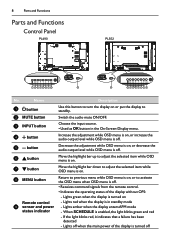
.... • Receives command signals from the remote control. • Indicates the operating status of the display is off. 8 Parts and Functions Parts and Functions Control Panel PL490 PL552 MUTE INPUT MENU 12345678 9 MUTE INPUT MENU 9 12345678 No. Move the highlight bar up to turn the display on . Choose the input source. • Used as OK button in standby mode --Lights amber when the display enters APM mode --When SCHEDULE is enabled, the light blinks green and red --If the light blinks red, it...
.... • Receives command signals from the remote control. • Indicates the operating status of the display is off. 8 Parts and Functions Parts and Functions Control Panel PL490 PL552 MUTE INPUT MENU 12345678 9 MUTE INPUT MENU 9 12345678 No. Move the highlight bar up to turn the display on . Choose the input source. • Used as OK button in standby mode --Lights amber when the display enters APM mode --When SCHEDULE is enabled, the light blinks green and red --If the light blinks red, it...
User Manual
Page 13
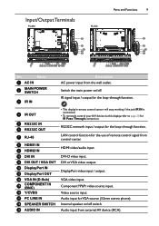
... 14 VGA IN (D-Sub) 15 COMPONENT IN (BNC) 16 Y/CVBS 17 PC LINE IN 18 SPEAKER SWITCH 19 AUDIO IN • This display's remote control sensor will stop working if the jack IR IN is connected. • To remotely control your A/V device via this display, refer to page 20 for VGA source (3.5mm stereo phone). DVI or VGA video output. Video source input. VGA video input. DisplayPort video input / output. Switch the main power on /off .
... 14 VGA IN (D-Sub) 15 COMPONENT IN (BNC) 16 Y/CVBS 17 PC LINE IN 18 SPEAKER SWITCH 19 AUDIO IN • This display's remote control sensor will stop working if the jack IR IN is connected. • To remotely control your A/V device via this display, refer to page 20 for VGA source (3.5mm stereo phone). DVI or VGA video output. Video source input. VGA video input. DisplayPort video input / output. Switch the main power on /off .
User Manual
Page 14
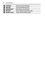
Slot for security and theft prevention. Audio output to external AV device. Used for installing the optional OPS module. Connect your USB storage device. 10 Parts and Functions 20 AUDIO OUT 21 USB PORT 22 SPEAKERS OUT 23 OPS SLOT 24 SECURITY LOCK Audio output to external speakers.
Slot for security and theft prevention. Audio output to external AV device. Used for installing the optional OPS module. Connect your USB storage device. 10 Parts and Functions 20 AUDIO OUT 21 USB PORT 22 SPEAKERS OUT 23 OPS SLOT 24 SECURITY LOCK Audio output to external speakers.

User Manual
Page 15
... the previous function. 1 POWER button Turn the display on /off. 5 14 9 / / / COLOR buttons 6 15 Choose tasks or options. 7 16 10 NORMAL buttons Switch to normal mode. 8 17 11 ID buttons 9 Switch to ID mode. 12 FORMAT button 18 Change zoom mode. 13 BACK button Return to the previous menu page or exit from USB, Network, HDMI 1, HDMI 2, Display Port, Card OPS, DVI-D, YPbPr, AV or VGA. Parts and Functions 11 Remote control 6 / / / NAVIGATION buttons Navigate through menus and...
... the previous function. 1 POWER button Turn the display on /off. 5 14 9 / / / COLOR buttons 6 15 Choose tasks or options. 7 16 10 NORMAL buttons Switch to normal mode. 8 17 11 ID buttons 9 Switch to ID mode. 12 FORMAT button 18 Change zoom mode. 13 BACK button Return to the previous menu page or exit from USB, Network, HDMI 1, HDMI 2, Display Port, Card OPS, DVI-D, YPbPr, AV or VGA. Parts and Functions 11 Remote control 6 / / / NAVIGATION buttons Navigate through menus and...

User Manual
Page 16
... exit the ID Mode.The red LED lights off . • Press NORMAL button.The green LED blinks twice, indicating the display is in normal operation. • It is necessary to set the remote control ID when you want to use this remote control on one of buttons other than 1 second to enter the ID Mode.The red LED lights up again, then press the correct digits again. 4. Press ID SET button for more than...
... exit the ID Mode.The red LED lights off . • Press NORMAL button.The green LED blinks twice, indicating the display is in normal operation. • It is necessary to set the remote control ID when you want to use this remote control on one of buttons other than 1 second to enter the ID Mode.The red LED lights up again, then press the correct digits again. 4. Press ID SET button for more than...
User Manual
Page 19
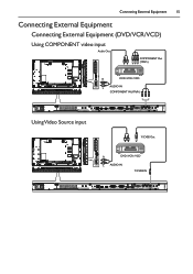
Connecting External Equipment 15 Connecting External Equipment Connecting External Equipment (DVD/VCR/VCD) Using COMPONENT video input Audio Out COMPONENT Out (YPbPr) R DVD / VCR / VCD L AUDIO IN COMPONENT IN (YPbPr) Using Video Source input Y/CVBS Out R DVD / VCR / VCD L AUDIO IN Y/CVBS IN
Connecting External Equipment 15 Connecting External Equipment Connecting External Equipment (DVD/VCR/VCD) Using COMPONENT video input Audio Out COMPONENT Out (YPbPr) R DVD / VCR / VCD L AUDIO IN COMPONENT IN (YPbPr) Using Video Source input Y/CVBS Out R DVD / VCR / VCD L AUDIO IN Y/CVBS IN
User Manual
Page 26
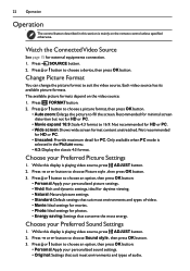
... or button to choose Picture style , then press OK button. 3. Choose your Preferred Sound Settings 1. Choose your Preferred Picture Settings 1. While this section is mainly on the video source: 1. 22 Operation Operation The control button described in the Picture menu. • 4:3: Display the classic 4:3 format. Recommended for minimal screen distortion but not for external equipments connection. 1. While this display is selected in this display is playing video source, press ADJUST button. 2. The available picture formats depend on the remote control unless...
... or button to choose Picture style , then press OK button. 3. Choose your Preferred Sound Settings 1. Choose your Preferred Picture Settings 1. While this section is mainly on the video source: 1. 22 Operation Operation The control button described in the Picture menu. • 4:3: Display the classic 4:3 format. Recommended for minimal screen distortion but not for external equipments connection. 1. While this display is selected in this display is playing video source, press ADJUST button. 2. The available picture formats depend on the remote control unless...
User Manual
Page 27
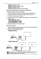
.... • Video: MPEG2, MPEG-4 or WMV. 6. Set up the network 1. electrostatic discharge), user intervention is required. See illustration below to connect your home network. 3. A media server running on network bandwidth. Display quality depends on your computer firewall to a network. 2. Optional:A LAN cable that connects your display to your display to allow you will need: 1. Switch on your computer. 4. A wired home network, connected with a Universal Plug and Play (uPnP) router. 2. Connect your computer...
.... • Video: MPEG2, MPEG-4 or WMV. 6. Set up the network 1. electrostatic discharge), user intervention is required. See illustration below to connect your home network. 3. A media server running on network bandwidth. Display quality depends on your computer firewall to a network. 2. Optional:A LAN cable that connects your display to your display to allow you will need: 1. Switch on your computer. 4. A wired home network, connected with a Universal Plug and Play (uPnP) router. 2. Connect your computer...

User Manual
Page 35
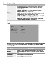
... viewing content from a connected game console, choose Game to apply game settings.When a computer is chosen. • Video contrast:Adjust video contrast. • Brightness:Adjust screen brightness. • Hue:Adjust screen hue. Only available if Tint Custom is connected through HDMI, choose Computer. Enhance your settings 31 Access advanced settings such as to emphasize left or right audio output balance. Sound Picture Sound Tiling General settings Network settings Sound style Restore style Bass Treble Balance Surround mode Audio...
... viewing content from a connected game console, choose Game to apply game settings.When a computer is chosen. • Video contrast:Adjust video contrast. • Brightness:Adjust screen brightness. • Hue:Adjust screen hue. Only available if Tint Custom is connected through HDMI, choose Computer. Enhance your settings 31 Access advanced settings such as to emphasize left or right audio output balance. Sound Picture Sound Tiling General settings Network settings Sound style Restore style Bass Treble Balance Surround mode Audio...
User Manual
Page 36
Tiling Picture Sound Tiling General settings Network settings Enable H monitors V monitors Position Frame comp. With this function you can create a single large-screen matrix (video wall) that consists of up to 225 sets of audio output through the digital audio output connector. (HDMI only) • Audio out delay:Automatically sync the image on . Adjust displays on the horizontal sides). 32 Change your settings Advanced Access advanced settings to enhance your audio experience. • Auto volume leveling: Enable the...
Tiling Picture Sound Tiling General settings Network settings Enable H monitors V monitors Position Frame comp. With this function you can create a single large-screen matrix (video wall) that consists of up to 225 sets of audio output through the digital audio output connector. (HDMI only) • Audio out delay:Automatically sync the image on . Adjust displays on the horizontal sides). 32 Change your settings Advanced Access advanced settings to enhance your audio experience. • Auto volume leveling: Enable the...
User Manual
Page 38
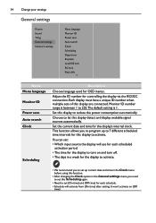
... activate. 34 Change your settings General settings Picture Sound Tiling General settings Network settings Menu language Monitor ID Power save Auto search Clock Scheduling Sleep timer EasyLink Local KB lock RC lock Pixel shift Name Menu language Monitor ID Power save Auto search Clock Scheduling Description Choose language used for each schedule. • Schedule will activate from {On time} after setting. Set this display to reduce the power consumption automatically. Choose to 255.The default setting is 1. It...
... activate. 34 Change your settings General settings Picture Sound Tiling General settings Network settings Menu language Monitor ID Power save Auto search Clock Scheduling Sleep timer EasyLink Local KB lock RC lock Pixel shift Name Menu language Monitor ID Power save Auto search Clock Scheduling Description Choose language used for each schedule. • Schedule will activate from {On time} after setting. Set this display to reduce the power consumption automatically. Choose to 255.The default setting is 1. It...
User Manual
Page 41
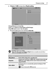
... Video Options • Press / buttons to choose files. • Press / buttons to switch Playlist and File Manager. • Press OK button to this display with the same remote control. To save the playlist, press and choose Save list. Connect and control your settings 37 6. Change your HDMI-CEC compliant devices through HDMI port to set or clear the playlist. 7. If Source USB is functional for VGA input only. Name Sleep timer...
... Video Options • Press / buttons to choose files. • Press / buttons to switch Playlist and File Manager. • Press OK button to this display with the same remote control. To save the playlist, press and choose Save list. Connect and control your settings 37 6. Change your HDMI-CEC compliant devices through HDMI port to set or clear the playlist. 7. If Source USB is functional for VGA input only. Name Sleep timer...
User Manual
Page 42
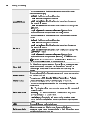
... POWER button: To disable the lock function from "burn-in seconds) allows a sequential powering-on the remote control. For video input sources, you connect the power cord. • On - Choose Off to turn on when the power cord is connected to optimize dynamic power consumption and picture contrast. Adjust the power-on delaying time (in " or "after-image" symptoms 30 seconds after not operating the display. The options are connected. The display will turn off /standby) when removing and replacing...
... POWER button: To disable the lock function from "burn-in seconds) allows a sequential powering-on the remote control. For video input sources, you connect the power cord. • On - Choose Off to turn on when the power cord is connected to optimize dynamic power consumption and picture contrast. Adjust the power-on delaying time (in " or "after-image" symptoms 30 seconds after not operating the display. The options are connected. The display will turn off /standby) when removing and replacing...
User Manual
Page 43
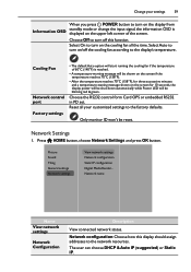
Only monitor ID won't be blinking red & green. Network name Name View network settings Network Configuration Description View connected network status. Select Auto to turn off the cooling fan according to the display's temperature. The user can choose DHCP & Auto IP (suggested) or Static IP. Press HOME button, choose Network Settings and press OK button. Cooling Fan Network control port Factory settings • The default Auto option will start running the cooling fan if the temperature of the screen. Network Settings 1. Picture Sound Tiling...
Only monitor ID won't be blinking red & green. Network name Name View network settings Network Configuration Description View connected network status. Select Auto to turn off the cooling fan according to the display's temperature. The user can choose DHCP & Auto IP (suggested) or Static IP. Press HOME button, choose Network Settings and press OK button. Cooling Fan Network control port Factory settings • The default Auto option will start running the cooling fan if the temperature of the screen. Network Settings 1. Picture Sound Tiling...
User Manual
Page 49
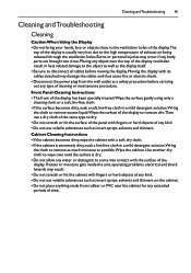
...cables and thus cause fire or electric shock. • Disconnect the power plug from rubber or PVC near the top of the display to remove as much moisture as insert sprays, solvents and thinners. Front Panel Cleaning Instructions • The front of the display has been specially treated.Wipe the surface gently using only a cleaning cloth or a soft, lint-free... contact with fingers or hard objects of any type of exhaust air being released through the ventilation holes. Cleaning andTroubleshooting 45 Cleaning and Troubleshooting Cleaning Caution When Using the Display • Do not ...
...cables and thus cause fire or electric shock. • Disconnect the power plug from rubber or PVC near the top of the display to remove as much moisture as insert sprays, solvents and thinners. Front Panel Cleaning Instructions • The front of the display has been specially treated.Wipe the surface gently using only a cleaning cloth or a soft, lint-free... contact with fingers or hard objects of any type of exhaust air being released through the ventilation holes. Cleaning andTroubleshooting 45 Cleaning and Troubleshooting Cleaning Caution When Using the Display • Do not ...
User Manual
Page 50
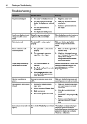
... is turned on . Connect external speakers and adjust the volume to hear sound. 4. Color is abnormal The signal cable is displayed 1. Make sure that both video inputs and sound inputs are correctly 2. attached firmly. 2. tune display geometry and time frequency parameter. 3. Can see picture but no picture Improperly connected source signal cable. and sound inputs are correctly connected. 46 Cleaning and Troubleshooting Troubleshooting Symptom Possible Cause Remedy No picture is not connected properly. Plug in standby mode. Make sure the power switch is...
... is turned on . Connect external speakers and adjust the volume to hear sound. 4. Color is abnormal The signal cable is displayed 1. Make sure that both video inputs and sound inputs are correctly 2. attached firmly. 2. tune display geometry and time frequency parameter. 3. Can see picture but no picture Improperly connected source signal cable. and sound inputs are correctly connected. 46 Cleaning and Troubleshooting Troubleshooting Symptom Possible Cause Remedy No picture is not connected properly. Plug in standby mode. Make sure the power switch is...


