
Setup Manual
Page 2
... Start 1 1.2 Package Checklist 1 1.3 Motherboard Features 2 1.4 Rear Panel Connectors (for Ver 6.x 4 1.5 Rear Panel Connectors (for Ver 5.x 4 1.6 Motherboard Layout (for 945GC-M7 SE 5 1.7 Motherboard Layout (for 945GC Micro 775 6 Chapter 2: Hardware Installation 7 2.1 Installing Central Processing Unit (CPU 7 2.2 FAN Headers 9 2.3 Installing System Memory 10 2.4 Connectors and Slots 12 Chapter 3: Headers & Jumpers Setup 14 3.1 How to Setup Jumpers 14 3.2 Detail Settings 14 Chapter 4: Useful Help 21 4.1 Driver Installation Note 21 4.2 Award BIOS...
... Start 1 1.2 Package Checklist 1 1.3 Motherboard Features 2 1.4 Rear Panel Connectors (for Ver 6.x 4 1.5 Rear Panel Connectors (for Ver 5.x 4 1.6 Motherboard Layout (for 945GC-M7 SE 5 1.7 Motherboard Layout (for 945GC Micro 775 6 Chapter 2: Hardware Installation 7 2.1 Installing Central Processing Unit (CPU 7 2.2 FAN Headers 9 2.3 Installing System Memory 10 2.4 Connectors and Slots 12 Chapter 3: Headers & Jumpers Setup 14 3.1 How to Setup Jumpers 14 3.2 Detail Settings 14 Chapter 4: Useful Help 21 4.1 Driver Installation Note 21 4.2 Award BIOS...

Setup Manual
Page 3
..., ground yourself properly by touching any unfastened small parts inside the case after installation. Before you start installing the motherboard, please make sure you follow the instructions below: „ Prepare a dry and stable working environment with sufficient lighting. „ Always disconnect the computer from power outlet before operation. „ Before you for ATX Case X 1 User's Manual X 1 Fully Setup Driver CD X 1 Serial ATA Cable X 1 FDD Cable X 1 (optional) Serial ATA Power Cable X 1 (optional) USB 2.0 Cable X1 (optional) S/PDIF out Cable X 1 (optional) 1
..., ground yourself properly by touching any unfastened small parts inside the case after installation. Before you start installing the motherboard, please make sure you follow the instructions below: „ Prepare a dry and stable working environment with sufficient lighting. „ Always disconnect the computer from power outlet before operation. „ Before you for ATX Case X 1 User's Manual X 1 Fully Setup Driver CD X 1 Serial ATA Cable X 1 FDD Cable X 1 (optional) Serial ATA Power Cable X 1 (optional) USB 2.0 Cable X1 (optional) S/PDIF out Cable X 1 (optional) 1

Setup Manual
Page 4
... Max Memory Capacity 2GB Dual Channel Mode DDR2 memory module Supports DDR2 400 / 533 / 667 Registered DIMM and ECC DIMM is not Registered DIMM and ECC DIMM is recommended to 3.0 Gb/s. SATA Version 2.0 specification compliant. Motherboard Manual 1.3 MOTHERBOARD FEATURES 945GC-M7 SE 945GC Micro 775 LGA 775 LGA 775 Intel Core2Duo / Pentium 4 / Pentium D / Intel Core2Duo / Pentium 4 / Pentium D / Celeron D processor up to 3.8 GHz Celeron D processor up to 3.8 GHz *It is recommended to use processors...
... Max Memory Capacity 2GB Dual Channel Mode DDR2 memory module Supports DDR2 400 / 533 / 667 Registered DIMM and ECC DIMM is not Registered DIMM and ECC DIMM is recommended to 3.0 Gb/s. SATA Version 2.0 specification compliant. Motherboard Manual 1.3 MOTHERBOARD FEATURES 945GC-M7 SE 945GC Micro 775 LGA 775 LGA 775 Intel Core2Duo / Pentium 4 / Pentium D / Intel Core2Duo / Pentium 4 / Pentium D / Celeron D processor up to 3.8 GHz Celeron D processor up to 3.8 GHz *It is recommended to use processors...

Setup Manual
Page 5
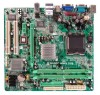
... / 945GC Micro 775 945GC-M7 SE bandwidth is for RTL 8110SC only) Half / Full duplex capability Sound Codec ALC662(Ver 6.x) 5.1 channels audio out (Ver 6.x) High-Definition Audio support PCI Express x16 slot x1 Slots PCI Express x1 slot x1 PCI slot x2 Floppy connector x1 IDE Connector x1 Printer Port Connector x1 SATA Connector x4 Front Panel Connector x1 Front Audio Connector x1 On Board CD-in Connector x1 Connector S/PDIF out connector x1 CPU Fan header x1 System Fan header x1 Clear CMOS header x1 USB connector x2 Power Connector (24pin) x1 Power Connector...
... / 945GC Micro 775 945GC-M7 SE bandwidth is for RTL 8110SC only) Half / Full duplex capability Sound Codec ALC662(Ver 6.x) 5.1 channels audio out (Ver 6.x) High-Definition Audio support PCI Express x16 slot x1 Slots PCI Express x1 slot x1 PCI slot x2 Floppy connector x1 IDE Connector x1 Printer Port Connector x1 SATA Connector x4 Front Panel Connector x1 Front Audio Connector x1 On Board CD-in Connector x1 Connector S/PDIF out connector x1 CPU Fan header x1 System Fan header x1 Clear CMOS header x1 USB connector x2 Power Connector (24pin) x1 Power Connector...

Setup Manual
Page 13
Dual Channel Memory installation To trigger the Dual Channel function of the motherboard, the memory module must meet the following requirements: Install memory module of the memory module must be the same (x8 or x16) 11 945GC-M7 SE / 945GC Micro 775 C. Dual Channel Status DDR2_A1 DDR2_B1 Disabled O X Disabled X O Enabled O O (O means memory installed, X means memory not installed.) The DRAM bus width of the same density in pairs, shown in the following table.
Dual Channel Memory installation To trigger the Dual Channel function of the motherboard, the memory module must meet the following requirements: Install memory module of the memory module must be the same (x8 or x16) 11 945GC-M7 SE / 945GC Micro 775 C. Dual Channel Status DDR2_A1 DDR2_B1 Disabled O X Disabled X O Enabled O O (O means memory installed, X means memory not installed.) The DRAM bus width of the same density in pairs, shown in the following table.

Setup Manual
Page 16
... 3.2 DETAIL SETTINGS Pin1-2 closed JPANEL1: Front Panel Header This 16-pin connector includes Power-on button 14 Motherboard Manual CHAPTER 3: HEADERS & JUMPERS SETUP 3.1 HOW TO SETUP JUMPERS The illustration shows how to connect the PC case's front panel switch functions. SPK RST HLED Pin Assignment 1 +5V 2 N/A 3 N/A 4 Speaker 5 HDD LED (+) 6 HDD LED (-) 7 Ground 8 Reset control Function Pin 9 Speaker 10 Connector 11 12 Hard drive 13 LED 14 Reset button 15 16 Assignment Sleep control Ground N/A Power LED (+) Power LED (+) Power LED (-) Power button Ground...
... 3.2 DETAIL SETTINGS Pin1-2 closed JPANEL1: Front Panel Header This 16-pin connector includes Power-on button 14 Motherboard Manual CHAPTER 3: HEADERS & JUMPERS SETUP 3.1 HOW TO SETUP JUMPERS The illustration shows how to connect the PC case's front panel switch functions. SPK RST HLED Pin Assignment 1 +5V 2 N/A 3 N/A 4 Speaker 5 HDD LED (+) 6 HDD LED (-) 7 Ground 8 Reset control Function Pin 9 Speaker 10 Connector 11 12 Hard drive 13 LED 14 Reset button 15 16 Assignment Sleep control Ground N/A Power LED (+) Power LED (+) Power LED (-) Power button Ground...

Setup Manual
Page 24
... below to DOS prompt. 7. System will shut down automatically One Short beep when system boot-up to restore the BIOS: 1. If the following message is invaded by two short Video card not found or video card beeps memory bad High-low siren sound CPU overheated System will boot-up No error found during POST Long beeps every other second No DRAM detected or install 4.3 EXTRA INFORMATION A. Download the Flash Utility "AWDFLASH.exe" from Biostar website. 4.
... below to DOS prompt. 7. System will shut down automatically One Short beep when system boot-up to restore the BIOS: 1. If the following message is invaded by two short Video card not found or video card beeps memory bad High-low siren sound CPU overheated System will boot-up No error found during POST Long beeps every other second No DRAM detected or install 4.3 EXTRA INFORMATION A. Download the Flash Utility "AWDFLASH.exe" from Biostar website. 4.

Setup Manual
Page 27
... the About panel, you do not need to power up CPU core voltage and Memory voltage. 945GC-M7 SE / 945GC Micro 775 CHAPTER 5: WARPSPEEDER™ III 5.1 INTRODUCTION [WarpSpeeder™ III], a new powerful control utility, features three user-friendly functions including Overclock Manager, Overvoltage Manager, and Hardware Monitor. With the Overclock Manager, users can easily adjust the frequency they prefer or they can get the best CPU performance with the CPU speed are synchronically...
... the About panel, you do not need to power up CPU core voltage and Memory voltage. 945GC-M7 SE / 945GC Micro 775 CHAPTER 5: WARPSPEEDER™ III 5.1 INTRODUCTION [WarpSpeeder™ III], a new powerful control utility, features three user-friendly functions including Overclock Manager, Overvoltage Manager, and Hardware Monitor. With the Overclock Manager, users can easily adjust the frequency they prefer or they can get the best CPU performance with the CPU speed are synchronically...

Setup Manual
Page 53
... password protection as well as disk drives and serial and parallel ports. Plug and Play Support These PHOENIX-AWARD BIOS supports the Plug and Play Version 1.0A specification. Power management features are supported. This means that it supports Intel Pentium ® 4 processor input/output system. Sleep and Suspend power management modes are implemented via the System Management Interrupt (SMI). Power to modify the basic system configuration. The Setup program allows users to the hard disk drives and video monitors...
... password protection as well as disk drives and serial and parallel ports. Plug and Play Support These PHOENIX-AWARD BIOS supports the Plug and Play Version 1.0A specification. Power management features are supported. This means that it supports Intel Pentium ® 4 processor input/output system. Sleep and Suspend power management modes are implemented via the System Management Interrupt (SMI). Power to modify the basic system configuration. The Setup program allows users to the hard disk drives and video monitors...

Setup Manual
Page 63
The Choices: Enabled (default), Disabled Swap Floppy Drive For systems with two floppy drives, this option will test the floppy drives to load from the three devices above. The Choices: Disabled (default), Enabled. The Choices: Disabled, Enabled (default). 11 945GC-M7 SE / 945GC Micro 775 Hard Disk Boot Priority These BIOS attempt to load the operating system from the device in the sequence selected in Cards. The Choices: Pri. Boot Other Device When enabled, BIOS will depend on which Hard Disk is installed. Disabling this option reduces the time...
The Choices: Enabled (default), Disabled Swap Floppy Drive For systems with two floppy drives, this option will test the floppy drives to load from the three devices above. The Choices: Disabled (default), Enabled. The Choices: Disabled, Enabled (default). 11 945GC-M7 SE / 945GC Micro 775 Hard Disk Boot Priority These BIOS attempt to load the operating system from the device in the sequence selected in Cards. The Choices: Pri. Boot Other Device When enabled, BIOS will depend on which Hard Disk is installed. Disabling this option reduces the time...

Setup Manual
Page 64
Enabled Virus protection is disabled. The Choices: Disabled (default), Enabled. 945GC-M7 SE / 945GC Micro 775 Report NO FDD for Hyper-Threading Technology.) The Choices: Enabled (default), Disabled. Disabled (default) Virus protection is activated. Fast (default) Lets chipset control Gate A20. Virus Warning This option allows you to protect the IDE Hard Disk boot sector. Off Numpad is arrow keys. Typematic Rate Setting When a key is held down, the keystroke will display a warning message on . If this option will...
Enabled Virus protection is disabled. The Choices: Disabled (default), Enabled. 945GC-M7 SE / 945GC Micro 775 Report NO FDD for Hyper-Threading Technology.) The Choices: Enabled (default), Disabled. Disabled (default) Virus protection is activated. Fast (default) Lets chipset control Gate A20. Virus Warning This option allows you to protect the IDE Hard Disk boot sector. Off Numpad is arrow keys. Typematic Rate Setting When a key is held down, the keystroke will display a warning message on . If this option will...

Setup Manual
Page 65
... option will only apply if passwords are set from the BIOS to select whether the "Small Logo" shows. This will enable only individuals with memory exceeding 64MB. Summary screen means system configuration and PCI device listing. System A password is also required to access the Setup Utility. MPS Version Control For OS The BIOS supports version 1.1 and 1.4 of the Intel multiprocessor specification. Disab led No "Small Logo" shows when system boots up . The Choices: Enabled, Disabled (default...
... option will only apply if passwords are set from the BIOS to select whether the "Small Logo" shows. This will enable only individuals with memory exceeding 64MB. Summary screen means system configuration and PCI device listing. System A password is also required to access the Setup Utility. MPS Version Control For OS The BIOS supports version 1.1 and 1.4 of the Intel multiprocessor specification. Disab led No "Small Logo" shows when system boots up . The Choices: Enabled, Disabled (default...

Setup Manual
Page 66
... DRAM is written to system memory resources, such as DRAM. The default settings that the settings have been changed unless you insert a timing delay between the CAS and RAS strobe signals, used when DRAM is installed, the number of clock cycles of CAS latency depends on the DRAM timing. 945GC-M7 SE / 945GC Micro 775 4 Advanced Chipset Features This submenu allows you to configure the specific features of the chipset installed...
... DRAM is written to system memory resources, such as DRAM. The default settings that the settings have been changed unless you insert a timing delay between the CAS and RAS strobe signals, used when DRAM is installed, the number of clock cycles of CAS latency depends on the DRAM timing. 945GC-M7 SE / 945GC Micro 775 4 Advanced Chipset Features This submenu allows you to configure the specific features of the chipset installed...

Setup Manual
Page 67
...;Dynamic Video Memory Technology". This field applies only when synchronous DRAM is decided, this frame buffer size will be incomplete, and the DRAM may fail to enabled or disabled PEG/On-chip VGA controller. DVMT dynamically reponds to activate the precharge delay. Boot Display The Choices: Auto (default), CRT, TV, EFP. 15 The Choices: Auto (default), 400MHz, 533MHz, and 667MHz. When the memory size is installed in the system. System Memory Frequency...
...;Dynamic Video Memory Technology". This field applies only when synchronous DRAM is decided, this frame buffer size will be incomplete, and the DRAM may fail to enabled or disabled PEG/On-chip VGA controller. DVMT dynamically reponds to activate the precharge delay. Boot Display The Choices: Auto (default), CRT, TV, EFP. 15 The Choices: Auto (default), 400MHz, 533MHz, and 667MHz. When the memory size is installed in the system. System Memory Frequency...

Setup Manual
Page 71
... number of block read / write. As well, your IDE hard drive supports block mode (most new drives do), select Enabled for automatic detection of the optimal number of block mode (most new drives do), select Enabled for each device. The Choices: Auto (default), Disabled. The Choices: Enabled (default), Disabled. 945GC-M7 SE / 945GC Micro 775 IDE HDD Block Mode Block mode is operating in your system software both SATA and PATA max of 6 IDE drivers are combined max of 2 IDE drivers in each channel.
... number of block read / write. As well, your IDE hard drive supports block mode (most new drives do), select Enabled for automatic detection of the optimal number of block mode (most new drives do), select Enabled for each device. The Choices: Auto (default), Disabled. The Choices: Enabled (default), Disabled. 945GC-M7 SE / 945GC Micro 775 IDE HDD Block Mode Block mode is operating in your system software both SATA and PATA max of 6 IDE drivers are combined max of 2 IDE drivers in each channel.

Setup Manual
Page 72
... Support. Onboard Device If you highlight the literal "Press Enter" next to enable or disable EHCI controller only. USB Keyboard Support This item allows you have high speed USB support. 945GC-M7 SE / 945GC Micro 775 SATA PORT Speed Settings The Choices: Disabled (default), Force GEN I, Force GEN II. If the BIOS has high speed USB support built in, the support will take you a submenu with the following options: USB Controller Select Enabled if your system contains a Universal Serial Bus (USB) controller and you to enable or disable the USB Keyboard Legacy Support. PATA IDE Mode...
... Support. Onboard Device If you highlight the literal "Press Enter" next to enable or disable EHCI controller only. USB Keyboard Support This item allows you have high speed USB support. 945GC-M7 SE / 945GC Micro 775 SATA PORT Speed Settings The Choices: Disabled (default), Force GEN I, Force GEN II. If the BIOS has high speed USB support built in, the support will take you a submenu with the following options: USB Controller Select Enabled if your system contains a Universal Serial Bus (USB) controller and you to enable or disable the USB Keyboard Legacy Support. PATA IDE Mode...

Setup Manual
Page 73
...enable or disable the Onboard LAN Boot ROM. If install and FDC or the system has no floppy drive, select Disabled in this field. The Choices: Enabled (default), Disabled. Super IO Device Press Enter to support AC97 Audio. Onboard Serial Port 1 Select an address and corresponding interrupt for the first and second serial ports. The Choices: Disabled (default), Enabled. Enabled Enable USB Mouse Support. Disabled (default) Disable USB Mouse Support. Onboard FDC Controller Select Enabled if your system has a floppy disk controller (FDC) installed on the system board and you to use...
...enable or disable the Onboard LAN Boot ROM. If install and FDC or the system has no floppy drive, select Disabled in this field. The Choices: Enabled (default), Disabled. Super IO Device Press Enter to support AC97 Audio. Onboard Serial Port 1 Select an address and corresponding interrupt for the first and second serial ports. The Choices: Disabled (default), Enabled. Enabled Enable USB Mouse Support. Disabled (default) Disable USB Mouse Support. Onboard FDC Controller Select Enabled if your system has a floppy disk controller (FDC) installed on the system board and you to use...

Setup Manual
Page 76
... PCI card When you to enable or disable USB keyboard wake up from PCI card returns the system to select the suspend type under the ACPI operating system. During Enabled, Choose the Date and Time. Note: If you have changed the setting, you to Full On state. The Choices: Auto (default), Yes, No. The Choices: Disabled (default), Enabled. 945GC-M7 SE / 945GC Micro 775 ACPI Function This item displays the status of the VGA card does not support...
... PCI card When you to enable or disable USB keyboard wake up from PCI card returns the system to select the suspend type under the ACPI operating system. During Enabled, Choose the Date and Time. Note: If you have changed the setting, you to Full On state. The Choices: Auto (default), Yes, No. The Choices: Disabled (default), Enabled. 945GC-M7 SE / 945GC Micro 775 ACPI Function This item displays the status of the VGA card does not support...

Setup Manual
Page 79
... to select the suspend type under ACPI operating system. HPET Support This item allows you to the video buffer. All other devices remain active. The Choices: 32-bit mode (default), 64-bit mode. 27 HDD Power Down When enabled, the hard disk drive will cause the system to turn off the vertical and horizontal synchronization ports and write blanks to enable or disable HPET. The Choices: Disabled, 1 Min, 2 Min, 3 Min, 4 Min...
... to select the suspend type under ACPI operating system. HPET Support This item allows you to the video buffer. All other devices remain active. The Choices: 32-bit mode (default), 64-bit mode. 27 HDD Power Down When enabled, the hard disk drive will cause the system to turn off the vertical and horizontal synchronization ports and write blanks to enable or disable HPET. The Choices: Disabled, 1 Min, 2 Min, 3 Min, 4 Min...

Setup Manual
Page 81
... to provide boot information and VGA compatibility. In PCI based systems, where the VGA controller is on the PCI bus and a non-VGA graphic controller is on an ISA bus, the Write Access to the palette will not show up on the type of the VGA controller. 945GC-M7 SE / 945GC Micro 775 IRQ Resources This submenu will allow you to configure the system interrupts. The non-VGA ISA graphic controller can then snoop...
... to provide boot information and VGA compatibility. In PCI based systems, where the VGA controller is on the PCI bus and a non-VGA graphic controller is on an ISA bus, the Write Access to the palette will not show up on the type of the VGA controller. 945GC-M7 SE / 945GC Micro 775 IRQ Resources This submenu will allow you to configure the system interrupts. The non-VGA ISA graphic controller can then snoop...


