

GEFORCE 6100 AM2 manual
Page 2
... Package Checklist 1 1.3 Motherboard Features 2 1.4 Rear Panel Connectors 3 1.5 Motherboard Layout 4 Chapter 2: Hardware Installation 5 2.1 Installing Central Processing Unit (CPU 5 2.2 FAN Headers 7 2.3 Installing System Memory 8 2.4 Connectors and Slots 10 Chapter 3: Headers & Jumpers Setup 12 3.1 How to Setup Jumpers 12 3.2 Detail Settings 12 Chapter 4: NVIDIA RAID Functions 20 4.1 Operation System 20 4.2 Raid Arrays 20 4.3 How RAID Works 20 Chapter 5: Useful Help 22 5.1 Driver Installation Note 22 5.2 Award BIOS Beep Code 23 5.3 Extra...
... Package Checklist 1 1.3 Motherboard Features 2 1.4 Rear Panel Connectors 3 1.5 Motherboard Layout 4 Chapter 2: Hardware Installation 5 2.1 Installing Central Processing Unit (CPU 5 2.2 FAN Headers 7 2.3 Installing System Memory 8 2.4 Connectors and Slots 10 Chapter 3: Headers & Jumpers Setup 12 3.1 How to Setup Jumpers 12 3.2 Detail Settings 12 Chapter 4: NVIDIA RAID Functions 20 4.1 Operation System 20 4.2 Raid Arrays 20 4.3 How RAID Works 20 Chapter 5: Useful Help 22 5.1 Driver Installation Note 22 5.2 Award BIOS Beep Code 23 5.3 Extra...

GEFORCE 6100 AM2 manual
Page 3
... and stable working environment with sufficient lighting. „ Always disconnect the computer from power outlet before operation. „ Before you for ATX Case X 1 User's Manual X 1 Fully Setup Driver CD X 1 Serial ATA Cable X 1 (optional) Serial ATA Power Cable X 1 (optional) USB 2.0 Cable X1 (optional) S/PDIF out Cable X 1 (optional) 1 GeForce 6100 AM2 CHAPTER 1: INTRODUCTION 1.1 BEFORE YOU START Thank you take the motherboard out from dangerous area, such as heat source, humid air and water. 1.2 PACKAGE CHECKLIST FDD Cable X 1 HDD Cable X 1 Rear I/O Panel for...
... and stable working environment with sufficient lighting. „ Always disconnect the computer from power outlet before operation. „ Before you for ATX Case X 1 User's Manual X 1 Fully Setup Driver CD X 1 Serial ATA Cable X 1 (optional) Serial ATA Power Cable X 1 (optional) USB 2.0 Cable X1 (optional) S/PDIF out Cable X 1 (optional) 1 GeForce 6100 AM2 CHAPTER 1: INTRODUCTION 1.1 BEFORE YOU START Thank you take the motherboard out from dangerous area, such as heat source, humid air and water. 1.2 PACKAGE CHECKLIST FDD Cable X 1 HDD Cable X 1 Rear I/O Panel for...
GEFORCE 6100 AM2 manual
Page 4
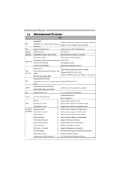
...Each connector supports 2 IDE device x2 Each connector supports 1 SATA devices x1 Supports front panel facilities x1 Supports front panel audio function x1 Supports CD audio-in GeForce 6100 Chipset Max Shared Video Memory is not supported Integrated IDE Controller IDE Ultra DMA 33 / 66 / 100 / 133 Bus Master supports PIO Mode 0~4, Mode SATA II Integrated Serial ATA Controller Data transfer rates up to 3 Gb/s. SATA Version 2.0 specification compliant. Motherboard Manual 1.3 MOTHERBOARD FEATURES SPEC Socket AM2 AMD 64 Architecture enables 32 and 64 bit computing CPU AMD...
...Each connector supports 2 IDE device x2 Each connector supports 1 SATA devices x1 Supports front panel facilities x1 Supports front panel audio function x1 Supports CD audio-in GeForce 6100 Chipset Max Shared Video Memory is not supported Integrated IDE Controller IDE Ultra DMA 33 / 66 / 100 / 133 Bus Master supports PIO Mode 0~4, Mode SATA II Integrated Serial ATA Controller Data transfer rates up to 3 Gb/s. SATA Version 2.0 specification compliant. Motherboard Manual 1.3 MOTHERBOARD FEATURES SPEC Socket AM2 AMD 64 Architecture enables 32 and 64 bit computing CPU AMD...

GEFORCE 6100 AM2 manual
Page 5
... to monitor. CMOS clear header USB connector Power Connector (24pin) Power Connector (4pin) PS/2 Keyboard PS/2 Mouse Back Panel I/O Serial Port VGA port LAN port USB Port Audio Jack Board Size 209.98 x 243.84 (mm) Special Features NVIDIA nTunes RAID 0 / 1 support OS Support Windows 2K / XP GeForce 6100 AM2 SPEC x1 Restore CMOS data to factory default x2 Each connector supports 2 front panel USB ports x1 Connects to Power supply x1 Connects to Power supply x1 Connects to PS/2 Keyboard x1 Connects to PS/2 Mouse x1 Provide RS-232 Serial connection x1 Connects to USB devices x3...
... to monitor. CMOS clear header USB connector Power Connector (24pin) Power Connector (4pin) PS/2 Keyboard PS/2 Mouse Back Panel I/O Serial Port VGA port LAN port USB Port Audio Jack Board Size 209.98 x 243.84 (mm) Special Features NVIDIA nTunes RAID 0 / 1 support OS Support Windows 2K / XP GeForce 6100 AM2 SPEC x1 Restore CMOS data to factory default x2 Each connector supports 2 front panel USB ports x1 Connects to Power supply x1 Connects to Power supply x1 Connects to PS/2 Keyboard x1 Connects to PS/2 Mouse x1 Provide RS-232 Serial connection x1 Connects to USB devices x3...

GEFORCE 6100 AM2 manual
Page 9
Connect the fan cable to the connector while matching the black wire to GND. JCFAN1: CPU Fan Header JCFAN1 4 1 Pin Assignment 1 Ground 2 +12V 3 FAN RPM rate sense 4 Smart Fan Control JNFAN1: North Bridge Fan Header JSFAN1: System Fan Header 1 JNFAN1 (optional) JNFAN1 Pin Assignment 1 Ground 2 +12V 3 FAN RPM rate sense 1 JSFAN1 JSFAN1 Pin Assignment 1 Ground 2 +12V 3 FAN RPM rate sense Note: The JCFAN1 Supports 4-pin head connector, and JSFANandJNFAN1 support 3-pin head connector. GeForce 6100 AM2 2.2 FAN HEADERS These fan headers support cooling-fans built in ...
Connect the fan cable to the connector while matching the black wire to GND. JCFAN1: CPU Fan Header JCFAN1 4 1 Pin Assignment 1 Ground 2 +12V 3 FAN RPM rate sense 4 Smart Fan Control JNFAN1: North Bridge Fan Header JSFAN1: System Fan Header 1 JNFAN1 (optional) JNFAN1 Pin Assignment 1 Ground 2 +12V 3 FAN RPM rate sense 1 JSFAN1 JSFAN1 Pin Assignment 1 Ground 2 +12V 3 FAN RPM rate sense Note: The JCFAN1 Supports 4-pin head connector, and JSFANandJNFAN1 support 3-pin head connector. GeForce 6100 AM2 2.2 FAN HEADERS These fan headers support cooling-fans built in ...

GEFORCE 6100 AM2 manual
Page 11
C. Dual Channel Memory installation GeForce 6100 AM2 To trigger the Dual Channel function of the motherboard, the memory module must be the same (x8 or x16) 9 Duual Channel Status DIMMA1 DIMMB1 DIMMA2 DIMMB2 Enabled O O X X Enabled X X O O Enabled O O O O (O means memory installed, X means memory not installed.) The DRAM bus width of the same density in pairs, shown in the following requirements: Install memory module of the memory module must meet the following table.
C. Dual Channel Memory installation GeForce 6100 AM2 To trigger the Dual Channel function of the motherboard, the memory module must be the same (x8 or x16) 9 Duual Channel Status DIMMA1 DIMMB1 DIMMA2 DIMMB2 Enabled O O X X Enabled X X O O Enabled O O O O (O means memory installed, X means memory not installed.) The DRAM bus width of the same density in pairs, shown in the following requirements: Install memory module of the memory module must meet the following table.

GEFORCE 6100 AM2 manual
Page 12
... 2 1 IDE2 IDE1 10 The first hard drive should always be connected to four hard disk drives. It has two HDD connectors IDE1 (primary) and IDE2 (secondary). This connector supports the provided floppy drive ribbon cables. 34 33 2 1 IDE1/IDE2: Hard Disk Connectors The motherboard has a 32-bit Enhanced PCI IDE Controller that supports 360K, 720K, 1.2M, 1.44M and 2.88M floppy disk types. Motherboard Manual 2.4 CONNECTORS AND SLOTS FDD1: Floppy Disk Connector The motherboard provides a standard floppy disk connector that provides PIO Mode 0~4, Bus Master, and Ultra DMA 33...
... 2 1 IDE2 IDE1 10 The first hard drive should always be connected to four hard disk drives. It has two HDD connectors IDE1 (primary) and IDE2 (secondary). This connector supports the provided floppy drive ribbon cables. 34 33 2 1 IDE1/IDE2: Hard Disk Connectors The motherboard has a 32-bit Enhanced PCI IDE Controller that supports 360K, 720K, 1.2M, 1.44M and 2.88M floppy disk types. Motherboard Manual 2.4 CONNECTORS AND SLOTS FDD1: Floppy Disk Connector The motherboard provides a standard floppy disk connector that provides PIO Mode 0~4, Bus Master, and Ultra DMA 33...

GEFORCE 6100 AM2 manual
Page 13
... motherboard is designated as 32 bits. This PCI slot is equipped with 2 standard PCI slots. PCI-Express 1.0a compliant. - PCI1 PCI2 11 Data transfer bandwidth up to 250MB/s per direction, for expansion cards. PCI-Express supports a raw bit-rate of 4GB/s simultaneously per direction; 500MB/s in total. - PCI stands for Peripheral Component Interconnect, and it is a bus standard for an aggregate of 8GB/s totally. GeForce 6100 AM2 PCI-Ex16: PCI-Express...
... motherboard is designated as 32 bits. This PCI slot is equipped with 2 standard PCI slots. PCI-Express 1.0a compliant. - PCI1 PCI2 11 Data transfer bandwidth up to 250MB/s per direction, for expansion cards. PCI-Express supports a raw bit-rate of 4GB/s simultaneously per direction; 500MB/s in total. - PCI stands for Peripheral Component Interconnect, and it is a bus standard for an aggregate of 8GB/s totally. GeForce 6100 AM2 PCI-Ex16: PCI-Express...

GEFORCE 6100 AM2 manual
Page 14
... user to set up jumpers. SPK RST HLED Pin Assignment 1 +5V 3 N/A 5 N/A 7 Speaker 9 HDD LED (+) 11 HDD LED (-) 13 Ground 15 Reset control Function Pin Assignment 2 Sleep control Speaker Connector 4 Ground 6 N/A 8 Power LED (+) Hard drive LED 10 Power LED (+) 12 Power LED (-) Reset button 14 Power button 16 Ground Function Sleep button N/A Power LED Power-on , Reset, HDD LED, Power LED, Sleep button, speaker and IrDA Connection. PWR_LED SLP On/Off ++ - 2 16 1 15 +- Pin opened Pin closed Pin1-2 closed 3.2 DETAIL SETTINGS JPANEL1: Front Panel Header...
... user to set up jumpers. SPK RST HLED Pin Assignment 1 +5V 3 N/A 5 N/A 7 Speaker 9 HDD LED (+) 11 HDD LED (-) 13 Ground 15 Reset control Function Pin Assignment 2 Sleep control Speaker Connector 4 Ground 6 N/A 8 Power LED (+) Hard drive LED 10 Power LED (+) 12 Power LED (-) Reset button 14 Power button 16 Ground Function Sleep button N/A Power LED Power-on , Reset, HDD LED, Power LED, Sleep button, speaker and IrDA Connection. PWR_LED SLP On/Off ++ - 2 16 1 15 +- Pin opened Pin closed Pin1-2 closed 3.2 DETAIL SETTINGS JPANEL1: Front Panel Header...

GEFORCE 6100 AM2 manual
Page 15
GeForce 6100 AM2 ATX Power Source Connector: JATXPWR1 JATXPWR1 allows user to connect 24-pin power connector on the ATX power supply. 12 24 1 13 Pin Assignment Pin Assignment 1 +3.3V 13 +3.3V 2 +3.3V 14 -12V 3 Ground 15 Ground 4 +5V 16 PS_ON 5 Ground 17 Ground 6 +5V 18 Ground 7 Ground 19 Ground 8 PW_OK 20 NC 9 Standby Voltage+5V 21 +5V 10 +12V 22 +5V 11 +12V 23 +5V 12 +3.3V 24 Ground 13
GeForce 6100 AM2 ATX Power Source Connector: JATXPWR1 JATXPWR1 allows user to connect 24-pin power connector on the ATX power supply. 12 24 1 13 Pin Assignment Pin Assignment 1 +3.3V 13 +3.3V 2 +3.3V 14 -12V 3 Ground 15 Ground 4 +5V 16 PS_ON 5 Ground 17 Ground 6 +5V 18 Ground 7 Ground 19 Ground 8 PW_OK 20 NC 9 Standby Voltage+5V 21 +5V 10 +12V 22 +5V 11 +12V 23 +5V 12 +3.3V 24 Ground 13

GEFORCE 6100 AM2 manual
Page 17
JUSBV2: USB ports at front panel (JUSB2/JUSB3) are powered by +5V standby voltage. 1 JUSBV1 1 1 1 3 3 Pin 1-2 close 1 1 3 3 JUSBV2 Pin 2-3 close Note: In order to support this function "Power-On system via USB device," "JUSBV1/ JUSBV2" jumper cap should be placed on Pin 2-3 individually. 15 JUSBV2: +5V for USB ports at JUSBLAN1. Pin 2-3 Close: JUSBV1: USB ports at JUSBLAN1 are powered by +5V standby voltage. GeForce 6100 AM2 JUSBV1/JUSBV2: Power Source Headers for USB Ports Pin 1-2 Close: JUSBV1: +5V for USB ports at front panel (JUSB2/JUSB3).
JUSBV2: USB ports at front panel (JUSB2/JUSB3) are powered by +5V standby voltage. 1 JUSBV1 1 1 1 3 3 Pin 1-2 close 1 1 3 3 JUSBV2 Pin 2-3 close Note: In order to support this function "Power-On system via USB device," "JUSBV1/ JUSBV2" jumper cap should be placed on Pin 2-3 individually. 15 JUSBV2: +5V for USB ports at JUSBLAN1. Pin 2-3 Close: JUSBV1: USB ports at JUSBLAN1 are powered by +5V standby voltage. GeForce 6100 AM2 JUSBV1/JUSBV2: Power Source Headers for USB Ports Pin 1-2 Close: JUSBV1: +5V for USB ports at front panel (JUSB2/JUSB3).

GEFORCE 6100 AM2 manual
Page 19
... motherboard. 1 3 Pin 1-2 Close: Normal Operation (default). 1 1 3 Pin 2-3 Close: Clear CMOS data. ※ Clear CMOS Procedures: 1. Set the jumper to the CMOS and show the message on the AC. 6. If the signal has been triggered, it allows user to restore the BIOS safe setting and the CMOS data, please carefully follow the procedures to "Pin 1-2 close ". 3. Remove AC power line. 2. Pin Assignment 1 Case open status. JCI1: Chassis Open Header (optional) This connector allows system to monitor PC case...
... motherboard. 1 3 Pin 1-2 Close: Normal Operation (default). 1 1 3 Pin 2-3 Close: Clear CMOS data. ※ Clear CMOS Procedures: 1. Set the jumper to the CMOS and show the message on the AC. 6. If the signal has been triggered, it allows user to restore the BIOS safe setting and the CMOS data, please carefully follow the procedures to "Pin 1-2 close ". 3. Remove AC power line. 2. Pin Assignment 1 Case open status. JCI1: Chassis Open Header (optional) This connector allows system to monitor PC case...

GEFORCE 6100 AM2 manual
Page 22
... data is up a large file into smaller blocks and performs disk reads and writes across multiple drives in parallel. Motherboard Manual CHAPTER 4: NVIDIA RAID FUNCTIONS 4.1 OPERATION SYSTEM z Supports Windows XP Home/Professional Edition, and Windows 2000 Professional. 4.2 RAID ARRAYS NVRAID supports the following types of the RAID set based on the platform. Uses: Intended for non-critical data requiring high data throughput, or any environment...
... data is up a large file into smaller blocks and performs disk reads and writes across multiple drives in parallel. Motherboard Manual CHAPTER 4: NVIDIA RAID FUNCTIONS 4.1 OPERATION SYSTEM z Supports Windows XP Home/Professional Edition, and Windows 2000 Professional. 4.2 RAID ARRAYS NVRAID supports the following types of the RAID set based on the platform. Uses: Intended for non-critical data requiring high data throughput, or any environment...

GEFORCE 6100 AM2 manual
Page 23
... expensive and less reliable media. GeForce 6100 AM2 RAID 1: Every read and write is actually carried out in parallel across 2 disk drives in the array. The mirrored (backup) copy of one drive. Should one drive fail, the controller switches to the other application that eliminates tedious manual backups to more detailed setup information, please refer to the Driver CD, or go to http...
... expensive and less reliable media. GeForce 6100 AM2 RAID 1: Every read and write is actually carried out in parallel across 2 disk drives in the array. The mirrored (backup) copy of one drive. Should one drive fail, the controller switches to the other application that eliminates tedious manual backups to more detailed setup information, please refer to the Driver CD, or go to http...

GEFORCE 6100 AM2 manual
Page 25
... or install 5.3 EXTRA INFORMATION A. In this Case, please follow the procedure below to DOS prompt. 7. Download the Flash Utility "AWDFLASH.exe" from Biostar website. 4. System will boot-up the system, it means the BIOS contents are corrupted. Insert the bootable disk into floppy disk. 5. Type "Awdflash xxxx.bf/sn/py/r" in DOS prompt. (xxxx means BIOS name.) 8. Make a bootable floppy disk. 2. System will work properly. 23 GeForce 6100 AM2 5.2 AWARD BIOS BEEP CODE Beep Sound...
... or install 5.3 EXTRA INFORMATION A. In this Case, please follow the procedure below to DOS prompt. 7. Download the Flash Utility "AWDFLASH.exe" from Biostar website. 4. System will boot-up the system, it means the BIOS contents are corrupted. Insert the bootable disk into floppy disk. 5. Type "Awdflash xxxx.bf/sn/py/r" in DOS prompt. (xxxx means BIOS name.) 8. Make a bootable floppy disk. 2. System will work properly. 23 GeForce 6100 AM2 5.2 AWARD BIOS BEEP CODE Beep Sound...

GEFORCE 6100 AM2 manual
Page 27
... turn 2. Back up the hard drive is in ; Reformat the hard drive. Cannot boot system after installing second hard drive. 1. No power to disk controller board. System inoperative. Screen message says "Invalid Configuration" or "CMOS Failure." Keyboard lights are on both ends are securely plugged in setup. Hard disk can be read and applications can be used but booting from hard disk 2. Call the drive manufacturers for compatibility with other drives. 25 GeForce 6100 AM2 5.4 TROUBLESHOOTING Probable Solution 1. Replace cable. drive, can be booted...
... turn 2. Back up the hard drive is in ; Reformat the hard drive. Cannot boot system after installing second hard drive. 1. No power to disk controller board. System inoperative. Screen message says "Invalid Configuration" or "CMOS Failure." Keyboard lights are on both ends are securely plugged in setup. Hard disk can be read and applications can be used but booting from hard disk 2. Call the drive manufacturers for compatibility with other drives. 25 GeForce 6100 AM2 5.4 TROUBLESHOOTING Probable Solution 1. Replace cable. drive, can be booted...
GEFORCE 6100 AM2 manual
Page 28
... Overclock Manager, users can easily adjust the frequency they prefer or they can get the best CPU performance with the CPU speed are synchronically shown on the other hand, helps to install DirectX 8.1.) 26 The cool Hardware Monitor smartly indicates the temperatures, voltage and CPU fan speed as well as the chipset information. Motherboard Manual CHAPTER 6: WARPSPEEDER™ 6.1 INTRODUCTION [WarpSpeeder™], a new powerful control utility, features three user-friendly functions including Overclock...
... Overclock Manager, users can easily adjust the frequency they prefer or they can get the best CPU performance with the CPU speed are synchronically shown on the other hand, helps to install DirectX 8.1.) 26 The cool Hardware Monitor smartly indicates the temperatures, voltage and CPU fan speed as well as the chipset information. Motherboard Manual CHAPTER 6: WARPSPEEDER™ 6.1 INTRODUCTION [WarpSpeeder™], a new powerful control utility, features three user-friendly functions including Overclock...

GEFORCE 6100 AM2 manual
Page 29
..., the Tray Icon utility and [WarpSpeeder™] utility will be automatically and immediately launched after you see the following dialog will change according to install. 2. When you click "Finish" button. Execute the setup execution file, and then the following dialog in this user manual will pop up. GeForce 6100 AM2 6.3 INSTALLATION 1. Please click "Next" button and follow the default procedure to your motherboard on hand. 27...
..., the Tray Icon utility and [WarpSpeeder™] utility will be automatically and immediately launched after you see the following dialog will change according to install. 2. When you click "Finish" button. Execute the setup execution file, and then the following dialog in this user manual will pop up. GeForce 6100 AM2 6.3 INSTALLATION 1. Please click "Next" button and follow the default procedure to your motherboard on hand. 27...

GEFORCE 6100 AM2 manual
Page 31
...; Display the CPU Speed, CPU external clock, Memory clock, AGP clock, and PCI clock information. With a user-friendly Status Animation, it can represent 3 overclock percentage stages: Man walking→overclock percentage from 100% ~ 110 % Panther running→overclock percentage from 110% ~ 120% Car racing→overclock percentage from 120% ~ above 29 GeForce 6100 AM2 2. c. b. the utility's first window you click the tray icon, [WarpSpeeder™] utility will see is Main Panel. Contains About, Voltage, Overclock...
...; Display the CPU Speed, CPU external clock, Memory clock, AGP clock, and PCI clock information. With a user-friendly Status Animation, it can represent 3 overclock percentage stages: Man walking→overclock percentage from 100% ~ 110 % Panther running→overclock percentage from 110% ~ 120% Car racing→overclock percentage from 120% ~ above 29 GeForce 6100 AM2 2. c. b. the utility's first window you click the tray icon, [WarpSpeeder™] utility will see is Main Panel. Contains About, Voltage, Overclock...

GEFORCE 6100 AM2 manual
Page 35
... mainboard's BIOS model and the Version number of all the chipset that are controlled by several separate chipset, [WarpSpeeder™] divide these features to overclocking. Note: Because the overclock, overvoltage, and hardware monitor features are related to separate panels. This property can also get model name and detail information in hints of [WarpSpeeder™] utility. If one chipset is not on board, the correlative button in Main Panel...
... mainboard's BIOS model and the Version number of all the chipset that are controlled by several separate chipset, [WarpSpeeder™] divide these features to overclocking. Note: Because the overclock, overvoltage, and hardware monitor features are related to separate panels. This property can also get model name and detail information in hints of [WarpSpeeder™] utility. If one chipset is not on board, the correlative button in Main Panel...


